


The system provides the ability to individually unlock the rear doors and the right front door using the door lock buttons.
Gearmotors are installed on the locks of each door. The gearmotor combines a DC electric motor with excitation from permanent magnets and a gearbox with a rack-and-pinion engagement.
Gearmotor 5 (figure 7-45) the left front door has a built-in switch, the contacts of which are switched when the lock button is moved or when the door lock drum is turned with a key. A signal is sent through the closed contacts of the switch to the electronic control unit 2 and it turns on all the gear motors. The gear motors turn the lock levers with rods and the locks are locked or unlocked.
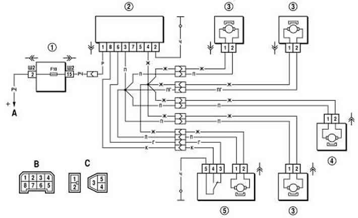
Figure 7-45. Schematic diagram of the door locking system:
1 - mounting block;
2 - control unit;
3 - passenger door lock motor reducer;
4 - rear door lock motor reducer;
5 - driver's door lock motor reducer;
A - to power sources;
B - diagram of conventional numbering of plugs in the control unit socket;
C - diagram of conventional numbering of plugs in the blocks of lock blocking motor reducers.
The control unit has an inertial switch, thanks to which the locks are unlocked when a moving vehicle hits an obstacle, i.e. in the event of an accident.
In case of malfunction, it is necessary to check the fuse, wires and their connections, control unit and gear motors. Replace faulty control unit and gear motors with new ones.
The specifics of the door locking system on vehicles with an electrical package control unit are described further in the section "Remote control system of the electrical package "Norma"".