


In the window lift mechanism, instead of the gear reducer used in mechanical window lifters, there is only a drum into the hole of which the output shaft of the gear motor is inserted.
The gearmotor consists of a worm gearbox and a DC electric motor with excitation from permanent magnets. Its design is similar to the design of the windshield wiper gearmotor. The gearmotor is reversible, the direction of rotation of the output shaft depends on the direction of the current in the anchor winding. To protect against overloads, it has a built-in thermal bimetallic fuse.
The wiring diagram for the electric window lifters is shown in Figure 7-44. Gearmotors 4 and 5 are switched on by switches 3 and 6 located on the armrest handles. Voltage is supplied to the switches via fuse F5 only when the ignition is on, when the contacts of relay 2 of the electric window lifters are closed. The relay used is type 904.3747-11 or 904.3747-11A. The relay is located to the left of the steering column on a bracket attached to the mounting block.
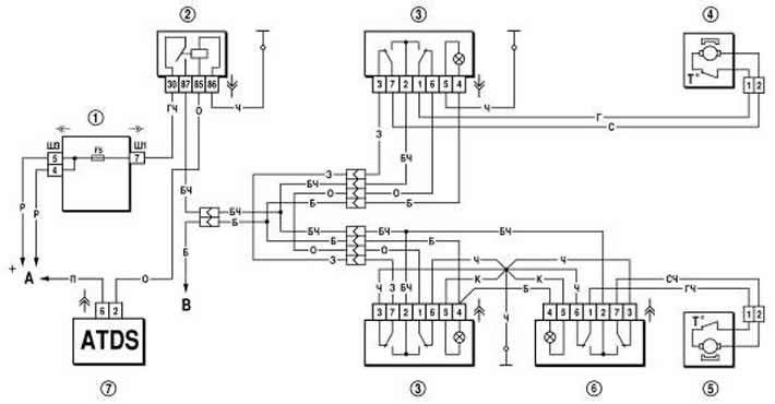
Figure 7-44. Door power window connection diagram:
1 - mounting block;
2 - electric window switch relay;
3 - Right front door electric window switch;
4 - motor reducer of electric window lifter of right front door;
5 - motor reducer of electric window lifter of left front door;
6 - Left front door electric window switch;
7 - APS control unit;
A - to power sources;
B - to the outdoor lighting switch.
If the electric windows do not work, you need to remove the door trims and check whether voltage is supplied to the gear motors, check the fuse and relay of the electric windows, repair the broken connections in the wires, and replace the faulty gear motor with a new one.