


Press down on rod 7 (figure 3-32) control lever 4 and use a screwdriver or some other pointed tool to remove the locking sleeve 12 from the groove on the lever rod. Remove the rod.
Disconnect the wiring harness connector from the speed sensor connector and the wires from the differential lock indicator lamp sensor. While turning the driveshafts, disconnect the driveshaft flanges from the transfer case shafts, and the intermediate driveshaft flange from the secondary shaft flange of the gearbox.
Unscrew two nuts 8 (figure 3-33) fastening the rear bracket 2 of the transfer case to the crossmember of the rear support. Remove the washers 7 and take out the bolts 4. Move the support part of the jack as far as it will go against the transfer case. After unscrewing the four nuts 8 fastening the brackets 3, lower and remove the transfer case from the jack.
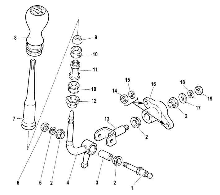
Figure 3-32. Control lever parts:
1 - control lever fork axle;
2 - bushing;
3 - spacer sleeve;
4 - control lever;
5 - washer;
6 - fork axle nut;
7 - control lever rod;
8 - handle;
9 - thrust pad;
10 - elastic bushing;
11 - spacer sleeve;
12 - locking sleeve;
13 - control lever fork;
14 - bracket mounting nut;
15 - washer;
16 - control lever bracket;
17 - thrust washer;
18 - washer;
19 - control lever fork nut.
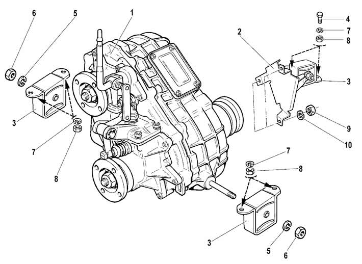
Figure 3-33. Transfer case suspension brackets:
1 - transfer case;
2 - rear suspension bracket;
3 - suspension bracket;
4 - bolt;
5 - washer;
6 - suspension axle nut;
7 - washer;
8 - suspension bracket nut;
9 - rear suspension bracket nut;
10 - washer.
Install the transfer case in the reverse order of removal.
[Information taken from the official website «chevyman»]