


Secure the transfer case on a disassembly stand, install the locking device and loosen the nuts securing the flanges on the drive shaft and on the front and rear axle drive shafts. After unscrewing the nut securing the rear axle drive shaft flange, remove the flange with the washer.
Having unscrewed the nuts securing the rear cover 31 (see figure 3-28), remove the cover assembly with the rear axle drive shaft.
Install the locking device on the flange of the drive shaft, engage any gear and unscrew the nuts securing the rear bearings of the drive and intermediate shafts. Then remove the mounting rings.
After unscrewing the four nuts securing the inspection hatch cover, remove the washers and the cover.
Install the locking device and, having unscrewed the nuts securing the flanges of the front axle drive shaft and the drive shaft, remove the flanges 12.
Unscrew bolt 24 (see figure 3-29) fastenings of the gear shift fork and carefully, closing the socket of the lock with your finger, remove the rod 12, fork 17, spacer sleeve 18, lock parts. Remove cover 4.
Remove the rod 15, unscrew the fastening nuts and remove the cover of the front bearing of the drive shaft. Then remove the speedometer drive housing with the driven gear 15 (see figure 3-28).
Having unscrewed two nuts 14 (see figure 3-32), remove the bracket with the control lever 4 of the transfer case. Then remove the front axle drive housing with the lever and the differential lock clutch.
Remove the front cover 4 (figure 3-34) together with the differential, then remove the differential bearing mounting ring and remove the bearing assembly with the differential from the front cover.
Remove the mounting rings from the rear bearings of the drive and intermediate shafts and remove both shafts from the transfer case housing: the drive and intermediate shafts.
Clamp the drive shaft in a vice and remove the thrust ring and rear bearing 11 (figure 3-35), using a universal puller, remove the low gear pinion 9 together with the bushing 10, the gear shift clutch 8, the clutch hub 7, and the high gear pinion 6 from the drive shaft.
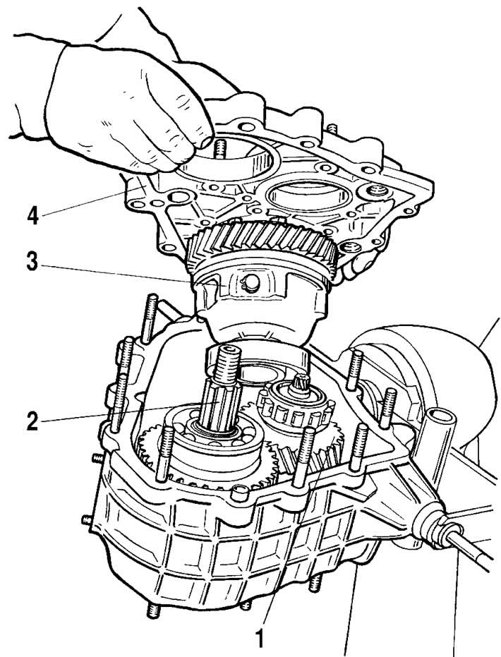
Figure 3-34. Removing the front cover of the transfer case:
1 - intermediate shaft;
2 - drive shaft;
3 - differential;
4 - front cover.
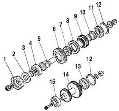
Figure 3-35. Details of the drive and intermediate shafts:
1 - flange;
2 - oil seal;
3 - thrust bearing ring;
4 - front bearing;
5 - drive shaft;
6 - top gear;
7 - hub;
8 - coupling;
9 - low gear;
10 - bushing;
11 - rear bearing;
12 - bearing mounting ring;
13 - intermediate shaft rear bearing;
14 - intermediate shaft;
15 - front bearing of the intermediate shaft.
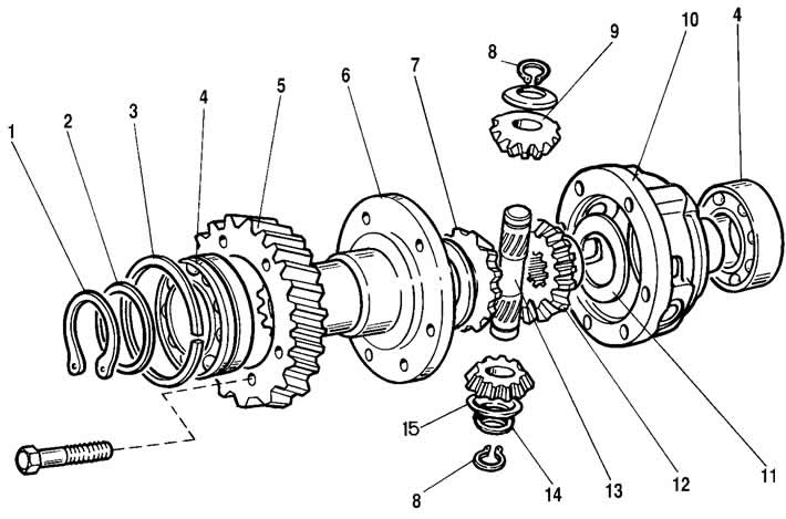
Figure 3-36. Transfer case differential parts:
1 - retaining ring;
2 - spring washer;
3 - bearing mounting ring;
4 - differential housing bearings;
5 - driven gear;
6 - front differential housing;
7 - front axle drive gear;
8 - satellite axle retaining ring;
9 - satellite;
10 - rear differential housing;
11 - support washer;
12 - rear axle drive gear;
13 - satellite axis;
14 - spring washer of the satellite axle;
15 - support washer.
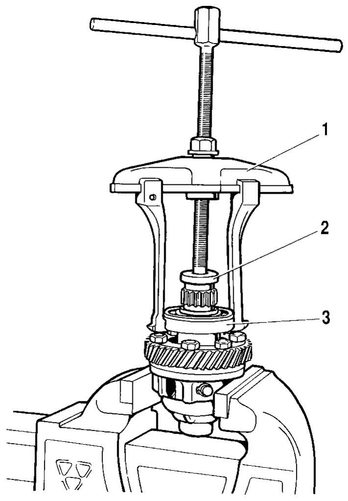
Figure 3-37. Pressing the bearing from the differential housing:
1 - puller;
2 - stop 67.7853-9559;
3 - bearing.
Disassemble the differential, for which:
- remove retaining ring 1 (figure 3-36) and spring washer 2 of the front bearing;
- remove the rear and front bearings from the differential housing (figure 3-37), using universal puller and stop 67.7853-9559;
- unscrew the bolts securing the differential driven gear, mark their relative positions on the differential housings with marks and separate the housings;
- remove the differential driven gear;
- remove retaining rings 8 (see figure 3-36) and spring washer 14, then press out the satellite axle and remove the satellites and drive gears of the drive axles with support washers.
Press out from the front cover 4 (see figure 3-34) outer race of front bearing 15 (see figure 3-35) intermediate shaft 14.
Press bearing 13 and inner bearing race 15 off intermediate shaft 14 using universal puller and stop 67.7853-9559.
Disassemble the back cover 31 (see figure 3-28), for what:
- remove the installation ring and press out bearing 36 with the rear axle drive shaft from the cover;
- remove the oil deflector and thrust ring (if available).
With the drive shaft clamped in a vice, press bearing 36 off the rear axle drive shaft using a universal puller and stop 67.7853-9559.
Disassemble the front axle drive housing, for which set the differential lock lever to the "unlocked" position and remove the differential lock clutch 5.
Loosen the cover mounting nuts 7 (see figure 3-29) front axle drive housing, remove the cover with differential lock lever 11, remove the spring and locking ball 19.
Loosen the bolt securing the differential lock fork 1, remove the rod 6 and fork 1, and remove the cover 4 from the rod.
Remove the installation ring and press out the bearing 8 from the crankcase (see figure 3-28) with shaft 11 of the front axle drive, remove the oil deflector 9 and the thrust ring (if available).
Clamp the front axle drive shaft 11 in a vice and press the bearing 8 off the shaft.
Remove the sealing ring from the front axle drive housing and press out the worn or damaged seals from the front axle drive housing, from the front bearing cover and the rear cover. Unscrew the nuts 6 (see figure 3-33) from the suspension cushion axles and remove the brackets 3 as an assembly.
Disassemble the front axle drive housing cover, for which remove the lock washer 8 (see figure 3-29), knock out axle 10 and remove differential lock lever 11 from cover 7, remove axle bushings 9. Unscrew switch 22 of the differential lock indicator lamp.
Disassemble the transfer case control lever mechanism by unscrewing nut 6 (see figure 3-32), remove axle 1 and bushings 2, spacer bushing 3 and control lever 4. Unscrew nut 19, remove fork 13 of control lever from control lever bracket 16 and remove bushings 2.
The transfer case assembly is carried out in the reverse order of disassembly, taking into account the following:
- assemble the center differential, aligning the marks on its housings so as not to disturb the balance of this unit;
- install a spring washer on the satellite axles from the side of the blind hole on the end of the axle;
- the axial clearance of each axle drive gear should be 0-0.10 mm, and the torque of resistance to rotation of the gears should not exceed 14.7 Nm (1.5 kgf·m). If the clearance is increased, replace the thrust washers with others of greater thickness; if the specified clearance cannot be achieved by installing the thickest support washers, replace the gears with new ones due to their excessive wear;
- the drive and intermediate shafts are installed in the transfer case housing simultaneously (see figure 3-38);
- press the bearings onto the differential housing using mandrel 67.7853-9558 (see figure 3-39);
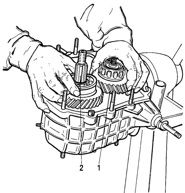
Figure 3-38. Installing the drive and intermediate shafts into the crankcase:
1 - intermediate shaft;
2 - drive shaft.
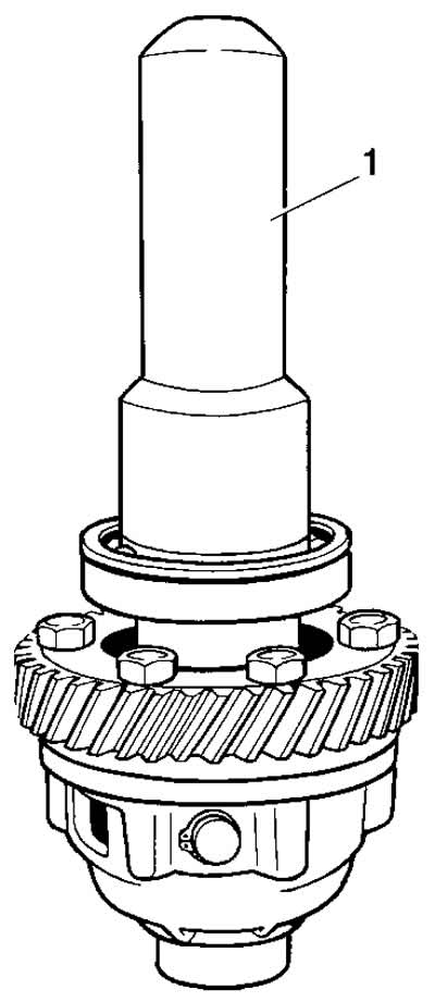
Figure 3-39. Pressing the bearing onto the differential housing:
1 - mandrel 67.7853-9558.
- before installing the seals into the covers and housings, lubricate the working surfaces of the seals with Litol-24 grease;
- before assembly, clean the surfaces of the rear cover, the drive shaft bearing cover and the speedometer drive housing from the remains of the old gasket and apply liquid gasket PS-1 along the perimeter of the surfaces in contact with the transfer case housing with a continuous roller with a diameter of 1...2 mm
- when tightening the nuts on the transfer case shafts, use a blunt chisel (see figure 3-40).
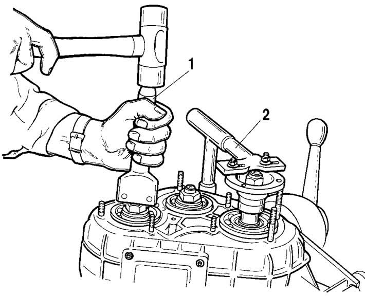
Figure 3-40. Tightening the rear axle drive shaft flange mounting nut:
1 - chisel;
2 - flange retainer.
After assembly, fill the transfer case with oil up to the lower edge of the filler hole.