


Contents: Compression measurement ↧ Checking the starter circuit ↧ Checking the ignition coil and its… ↧ Checking the fuel pump activation… ↧ Checking the pressure in the engine… ↧
Compression measurement
We perform a compression test to provide a general assessment of the technical condition of the cylinder-piston group parts and the engine valve mechanism.
Warm up the engine to operating temperature. Release the pressure in the engine fuel system (see Replacing the fuel filter) and do not install the fuel pump fuse in place. Unscrew the spark plugs from the cylinder head.
We disconnect the engine management system wiring harness connectors from the ignition coils.
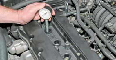
We install the compression tester tip into the spark plug hole of the cylinder head.
We connect the wire terminal to the negative terminal of the battery.
We turn the crankshaft with the starter while fully pressing the gas pedal for 2–4 seconds (the pressure gauge readings should stop increasing). We record the pressure gauge reading and release the pressure in the compression tester.
To properly evaluate the compression, the battery must be fully charged.
We check the compression in other engine cylinders in the same way.
The compression of a healthy engine should be within 11.0–13.0 bar, and the difference in readings between cylinders should not exceed 1.0 bar.
To determine the reasons for low compression, pour 10–15 cm³ of engine oil into the cylinder through the spark plug hole and repeat the measurement.
If the compression has increased by more than 2.0 bar during repeated measurements, the most likely cause of the malfunction is severe wear, sticking or breakage of the piston rings. If the pressure gauge readings have not increased after filling with oil, then most likely the valve plates do not fit tightly to the cylinder head seats. This can happen when the thermal clearances in the valve drive are violated, as well as with severe wear, burnout or damage to the plates or valve seats. The cause of the malfunction can only be determined once the engine has been disassembled.
Checking the starter circuit
If the starter does not work when the ignition key is turned to the START position, there may be a malfunction of both the starter itself and its activation circuit. We begin the troubleshooting by checking the fuse "Ef4" (30 A)…
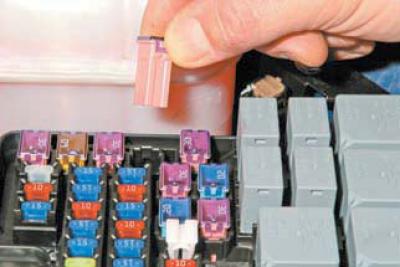
…which is located in the engine compartment mounting block.
If the fuse "Ef4" is intact, we proceed to check the functionality of the starter.
With the ignition off…
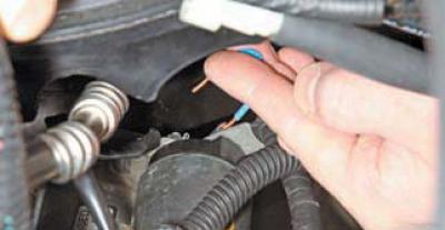
…we connect the control terminal of the traction relay and the tip of the wire coming from the positive terminal of the battery with a piece of insulated wire.
When performing this operation, care must be taken, as sparking may occur in the area where the traction relay terminals contact the wire section.
Do not short-circuit the wire to ground when connecting the terminals!
If the crankshaft turns, the starter is in good condition and the cause of the malfunction is a fault in its switching circuit. Otherwise, the starter or its traction relay is faulty.
If it is not possible to eliminate the fault in the circuit of a serviceable starter, then, if necessary, in this way (turn on the ignition and connect the terminals), you can start the engine and drive to the repair site.
Checking the ignition coil and its circuits
To check the functionality of the ignition coil, we release the pressure in the engine fuel system and do not install the fuel pump fuse in place (see Replacing the fuel filter). We remove from two spark plugs (serviced by the coil being tested) high-voltage wire tips and insert known good spark plugs into them.
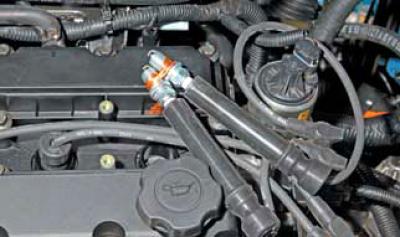
We connect the threaded parts of the spark plugs by wrapping them with bare multi-core copper wire.
To avoid electric shock, do not touch the spark plugs or high-voltage wire tips with your hands when turning the crankshaft with the starter.
The assistant, having turned the key in the ignition switch to the START position, turns the crankshaft.
If the spark plugs, high-voltage wires, ignition coil and its circuits are in good condition, sparks should regularly jump between the spark plug electrodes.
If this is not the case, it is necessary to check the power supply and control circuits of the coil.
To check the coil power supply circuit, we disconnect the engine management system wiring harness connector from it..
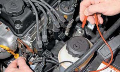
…and connect one tester probe between the engine ground and the terminal (which has a pink wire) wiring harness pads.
When the ignition is on, the device should record a voltage equal to the voltage at the battery terminals.
If the voltage value does not correspond to the norm, we check the integrity of the fuse "F2" of the interior mounting block, as well as the serviceability of the circuit (open or short to ground) between the terminal of the engine management system block and the terminal of the block that is connected to the contact part of the ignition switch. Please note that this circuit also includes relay K7.
To check the ignition coil control circuit, we use a tester with a 1.2 W lamp.
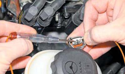
We connect the probes of the tester to the terminals of the ignition coil control wiring harness connector.
If the ignition coil control and power supply circuits are in good condition, the tester lamp should flash frequently when the crankshaft is turned by the starter.
Otherwise, check the circuits between the terminals of the ignition coil and the terminals of the ECU wiring harness connector.
If the power supply and control circuits of the ignition coil are in good order, but there is no spark on the spark plugs when checking (see above), then the coil itself should be checked.
To check the ignition coil, you should measure the resistance..
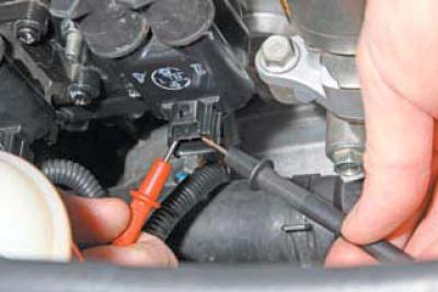
…primary (1.1 Ohm)…
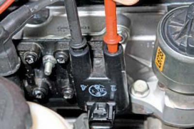
…and secondary (12–13 kOhm) windings.
If there is no spark on the spark plugs, you should also check the serviceability of the high-voltage wires.
The insulation and wire tips should not be damaged, and the resistance should fluctuate in the range from 1.7 to 4.0 kOhm, depending on the length of the wire.
Checking the fuel pump activation circuit
If the fuel pump does not turn on when the ignition is turned on (its operation can be controlled by ear) — there may be a malfunction of both the fuel pump itself and its activation circuit.
We begin checking the fuel pump activation circuit by assessing the integrity of fuse Ef18 (15 A), located in the engine compartment mounting block.
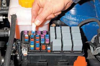
We replace the faulty fuel pump fuse with a new one, having first checked whether one of the terminals of the fuse socket is shorted to ground.
A malfunction in the fuel pump switching circuit may be caused by damage to the K7 pump relay in the mounting block.
To check the relay…
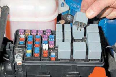
…we remove it from the mounting block and replace it with a known good one.
For this purpose, you can use the K8 window lift relay.
If the fuel pump turns on with the newly installed relay, then the fuel pump relay is out of order and must be replaced. Otherwise, it is necessary to check the power circuit and the control circuit of the fuel pump relay. To do this, remove the relay from the mounting block.
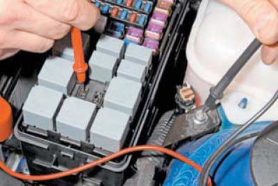
We measure the voltage between socket "30" of the mounting block and the "ground".
The device should record a voltage equal to the on-board network voltage. If this is not the case, the mounting block is faulty. We also measure the resistance between the "85" socket of the mounting block and the "ground". If the "ground" circuit is in good condition, the device should record a resistance of less than 1 Ohm.
With the ignition on, measure the voltage between socket "86" of the mounting block and the ground.
The device should record a voltage of about 12 V. If this does not happen, check the serviceability of the circuit between the "86" socket and the terminal of the ECU wiring harness block. If the circuit is serviceable, the ECU is faulty. Install the relay in place and disconnect the wiring harness block from the fuel module.
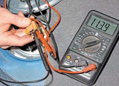
We measure the voltage between the terminals of the gray wire (the "+" power supply for the pump) and the adjacent black "ground" wire.
When the ignition is turned on, the device should record a voltage equal to the voltage of the on-board circuit for 2 seconds. Otherwise, we check the serviceability of the circuits between the "87" socket of the mounting block and the gray wire terminal of the fuel module wiring harness connector, as well as between the "ground" and the black wire terminal of the fuel module wiring harness connector.
Checking the pressure in the engine fuel system
To check the pressure in the fuel rail, you need a device that you can make yourself. For this, you will need a pressure gauge (for example, from a tire pump), oil and petrol resistant hose (with an internal diameter of 8 mm), tee (with an outer tube diameter of 8 mm) and worm gear clamps (6 pcs.).
We carry out the work on a cold engine. We release the pressure in the engine fuel system.
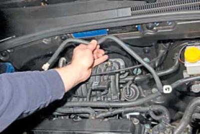
We remove the plastic tube connecting the steel tube that runs under the bottom of the car from the fuel tank and the fuel rail.
We put a hose on the outlet fitting of the steel tube running under the bottom of the car from the fuel tank and secure it with a clamp. We put the other end of the hose on the inlet fitting of the fuel rail and secure it with a clamp. In an accessible place, we cut the hose and install a tee, securing the hoses on the fittings of the tee with clamps.
We put a piece of hose on the free fitting of the tee, on the other end of which we install a pressure gauge, and secure the hose with clamps.
We turn on the ignition and check the tightness of the connections of the installed device.
We start the engine and when it is idling..
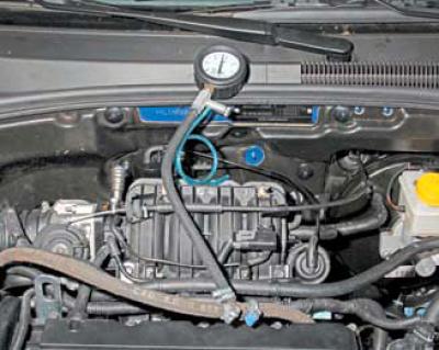
…we measure the fuel pressure in the system, which should be equal to 2.8–3.3 bar.
After the pump stops, the pressure may drop slightly and then stabilize for a while. If the pressure in the system is more than 3.3 bar, the fuel pressure regulator is faulty.
Low but stable fuel pressure may be caused by a clogged fuel filter or fuel module mesh filter, as well as a faulty pump or fuel pressure regulator. It is better to immediately replace the fuel filter with a new one, which we recommend always having in stock.
If the fuel pressure in the engine fuel system is low and continues to drop after the pump is turned off, the cause may be a leak in the fuel module connections, a faulty pressure regulator or pump, or leaky injectors.
A leaky injector can usually be identified by the dark color of its spray nozzle, which contains coked drops of fuel.
(The article is based on data from the website chevyman)