
Front door
Inner handle
1. Raise the glass all the way up and remove the inner door panel (see section 11).
2. Disconnect the lock rod from the handle.
3. Drill out the rivets that secure the handle to the door and remove the handle (see illustration).
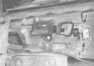
18.3. Drill out the rivets (indicated by arrows), locking handles (the photo shows a variant of the car from early years of production)
4. Installation is carried out in reverse order.
External handle
5. Remove the inner door panel (see section 11).
6. Unscrew the handle mounting nuts (see illustration).
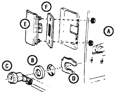
18.6. Front door handle details: A - handle and door mounting nuts, B - lock cylinder gasket, C - lock cylinder, D - latch, E - outer handle, F - outer handle gasket
7. Disconnect the handle from the lock rod and pull out the handle.
8. Installation is carried out in reverse order.
Lock
9. To remove the lock, first remove the inner door panel (see section 11) and disconnect the rods from the lock.
10. Disconnect the cylinder retainer and pull the lock cylinder out of the door (see illustration 18.6).
11. Working from the inside of the door, disconnect the lock button rod, the inside handle rod and the rod from the inside handle to the lock.
12. Loosen the lock screws and remove the lock (see illustration).
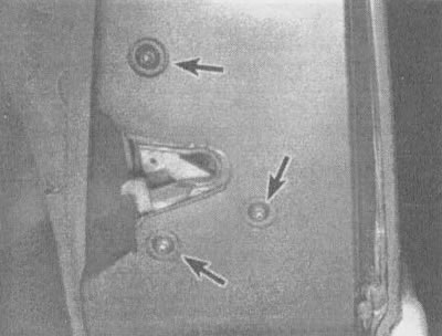
18.12. To remove the lock, unscrew the fixing screws (indicated by arrows) on the end of the door
Sliding door
Inner handle
13. Remove the inner panel of the sliding door (see section 11).
14. Disconnect the traction handle from the handle by squeezing the traction clamp and pushing it out of the assembly.
15. Loosen the screws of the inner handle and release the handle.
16. Installation is carried out in reverse order.
External handle
17. Remove the inner panel of the sliding door (see section 11).
18. Disconnect the rods from the handle by depressing the clamp and pushing the rods out of the assembly.
19. Unscrew the screws and nuts and release the handle.
20. Installation is carried out in reverse order.
Lock
21. Remove the inner door panel (see section 11).
22. Disconnect the lock cylinder rod by squeezing the clamp and pushing the rod out of the assembly.
23. Carefully remove the lock cylinder clamp and take out the lock.
24. Installation is carried out in reverse order.
Back door
25. Disconnect the cable from the negative terminal of the battery (see note at the beginning of this chapter) and remove the inner rear door panel (see section 11).
26. Disconnect the central locking connector (if any).
27. Disconnect the lock rods.
28. Remove the rod from the lock and drill out the rivets securing the lock mechanism to remove the lock from the door.
29. Installation is carried out in reverse order.
(The article was borrowed from the website: ChevyMan)