


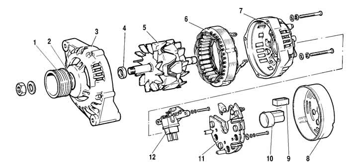
Figure 7-14. Generator parts:
1 - pulley;
2 - washer;
3 - front cover;
4 - distance ring;
5 - rotor;
6 - stator;
7 - back cover;
8 - casing;
9 - gasket;
10 - protective sleeve;
11 - rectifier block with capacitor;
12 - brush holder with voltage regulator.
Remove the protective sleeve 9 together with the gasket 10. Remove the rectifier unit with the capacitor from the rear cover by unscrewing the screws securing the phase terminals of the stator winding and the screw securing the capacitor to the cover. After this, if necessary, you can disconnect the capacitor from the rectifier unit by unscrewing the nut securing the capacitor wire to the "B+" terminal of the rectifier unit.
Unscrew the four tightening screws and detach the rear cover 7 with the stator 6 from the front cover 3 with the rotor 5. Detach the stator from the rear cover. If necessary, remove the bushing with the rear bearing of the rotor shaft from the rear cover.
Clamp the rotor in a vice and use a socket wrench to loosen the pulley 1 mounting nut. Remove the pulley, washer 2, front cover and spacer ring 4 from the rotor shaft.
The generator is assembled in the reverse order of disassembly. The spring washer of the pulley with its convex side should touch the nut.