


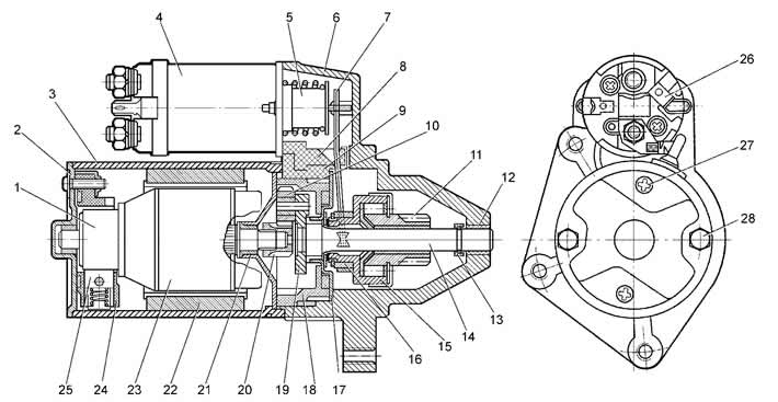
Figure 7-15. Starter 57.3708:
1 - collector;
2 - back cover;
3 - stator housing;
4 - traction relay;
5 - relay anchor;
6 - drive side cover;
7 - lever;
8 - lever bracket;
9 - sealing gasket;
10 - planetary gear;
11 - drive gear;
12 - lid insert;
13 - limiting ring;
14 - drive shaft;
15 - overrunning clutch;
16 - ring of the branch;
17 - drive shaft support with insert;
18 - internal gear;
19 - driver;
20 - central gear;
21 - armature shaft support;
22 - permanent magnet;
23 - anchor;
24 - brush holder;
25 - brush;
26 - output "50" of the traction relay;
27 - brush holder mounting screws;
28 - tie rod with nut.
Covers 2, 6 and the stator housing 3 are pulled together by two studs. The anchor shaft 23 rotates in two metal-ceramic inserts installed in cover 2 and support 21. Four permanent magnets 22 are fixed in the stator housing.
Rotation from the anchor shaft 23 is transmitted to the drive shaft 14 through a planetary gearbox, which consists of a central gear 20, three planetary gears 10, a carrier 19 and a gear 18 with internal engagement. The planetary gears rotate on needle bearings.
The starter connection diagram is shown in Figure 7-16. When the starter is turned on, voltage from the battery is supplied to both windings of the starter traction relay via the ignition switch and the power contacts of the additional starter relay (retractor II and retainer I). After the traction relay contacts are closed, the pull-in winding is switched off.
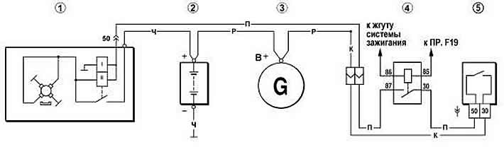
Figure 7-16. Starter wiring diagram:
1 - starter;
2 - battery;
3 - generator;
4 - additional starter relay;
5 - ignition switch.