
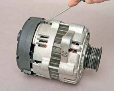
Using a screwdriver, press down four latches one by one..
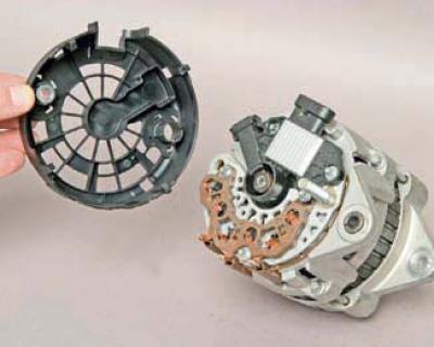
…and remove the plastic casing.
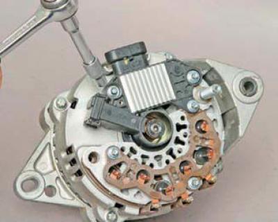
Using the E4 head, unscrew the three screws securing the brush holder and rectifier unit.
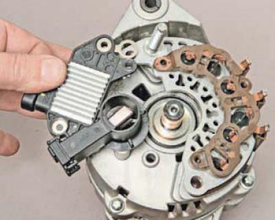
We remove the brush holder with the voltage regulator.
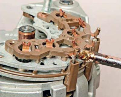
We unsolder the stator winding terminals from the rectifier unit terminals.
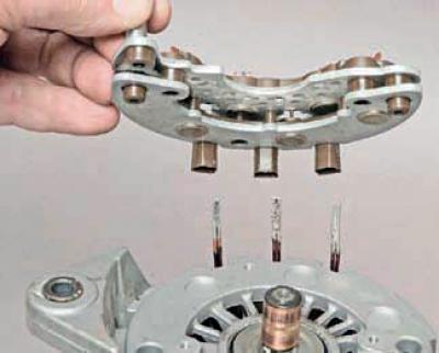
We remove the rectifier block.
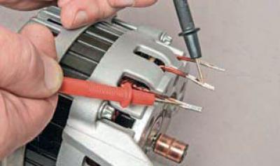
To check the rotor winding for open circuit and short circuit…
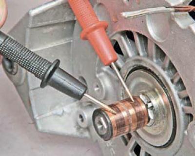
…we connect the ohmmeter probes to the contact rings.
We measure the resistance of the rotor winding, which should be within 1.7–2.3 Ohms. If the resistance is less than the specified value, then some of the turns of the rotor winding are shorted to each other; if the resistance is very high, (tends to infinity), then there is a break in the rotor windings. In both cases, the generator rotor must be replaced.
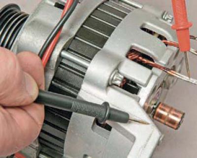
To check if the rotor windings are shorted to ground..
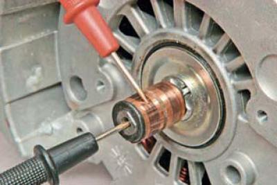
…we connect the ohmmeter probes to the rotor shaft and alternately to the contact rings.
The measured resistance should be very high (strive for infinity). If the ohmmeter shows a small resistance, it means that the rotor windings are shorted to ground. In this case, the generator rotor must be replaced.
To check the stator windings for breakage…
…using an ohmmeter, we measure the resistance between all the winding terminals one by one.
If the measured resistance tends to infinity, then there is a break in the stator windings and the generator stator must be replaced.
To check if the stator windings are shorted to ground..
…we connect the ohmmeter probes to the generator body and to each winding terminal in turn.
The measured resistance should be very high (strive for infinity). If the ohmmeter shows a small resistance, it means that the stator windings are shorted to ground. In this case, the generator stator must be replaced.
To check the "positive" diodes of the rectifier block..
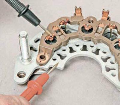
…we connect the red probe ("plus") of the ohmmeter to the "positive" plate of the block, and the black one ("minus") to the terminal of the "positive" diode.
We measure the resistance. Then we swap the ohmmeter probes and measure the resistance again. If the resistance is the same in both cases, then the diode is faulty and the rectifier unit needs to be replaced.
We check the other two diode circuits of the rectifier in the same way.
To check the "negative" diodes of the rectifier block..
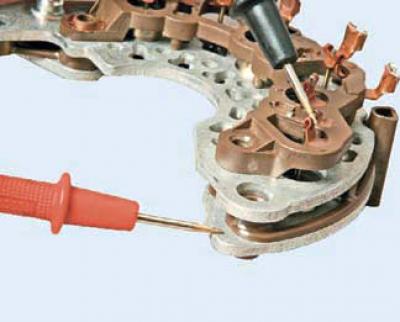
…we connect the red probe ("plus") of the ohmmeter to the "negative" plate of the block, and the black one ("minus") to the terminal of the "negative" diode.
Measure the resistance. Swap the ohmmeter probes and measure the resistance again. If the ohmmeter readings are the same in both cases, then the diode is faulty and the rectifier unit needs to be replaced. Similarly, check the other two diode circuits of the rectifier.
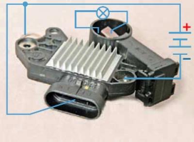
Voltage regulator test circuit.
To check the voltage regulator, connect a test lamp (1–5 W, 12 V) between the brushes.
We apply 12 V from a DC source: "+" to the "L" terminal and simultaneously to the "B+" terminal of the voltage regulator, "-" to the second terminal of the voltage regulator. The lamp should light up. When applying a voltage of 15–16 V, the lamp should go out.
If the lamp lights up in both cases, the regulator is damaged; if it does not light, there is a break in the circuit or the contact between the brushes and the terminals of the regulator is broken. In both cases, the regulator should be replaced.
We assemble the generator in reverse order.
[The original text can be found on the website CHEVYMAN.ru]