


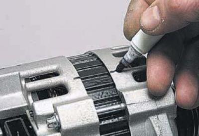
We mark the relative positions of the covers and the generator stator.
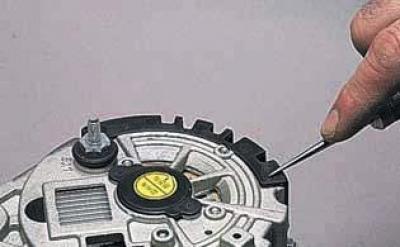
Using an awl or scriber, push the two pins that secure it into the plastic cover…
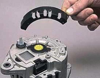
…and remove the lid.
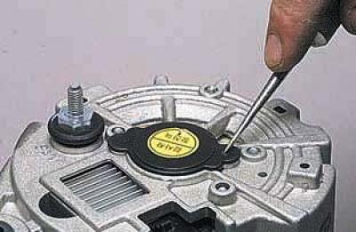
Using the same tool, push two locking pins into the protective cover of the generator rear bearing…
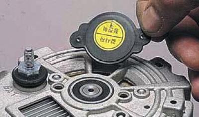
…and remove the lid.
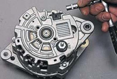
Using the E8 head, unscrew the three screws holding the front and rear covers of the generator.
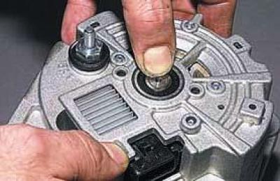
We remove the rear cover together with the stator, pushing the bearing out of the cover.
We unscrew the pulley mounting nut.
This work can be done in two ways.
In the first method, we put a 24 mm head on the pulley mounting nut.
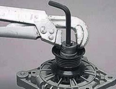
Holding the rotor shaft with an 8 mm Allen key and turning the head with a pipe wrench, unscrew the nut.
In the second method, we put a 24 mm head with a ratchet on the nut.
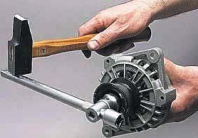
Holding the rotor from turning with your hand, we hit the handle with a hammer and unscrew the nut.
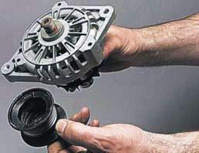
We remove the pulley from the rotor shaft..
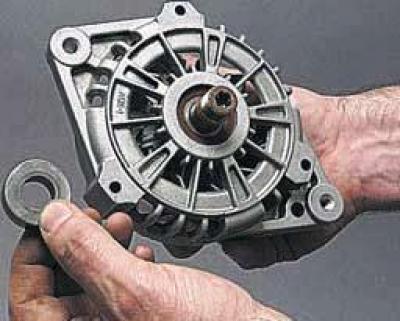
…and the bushing.
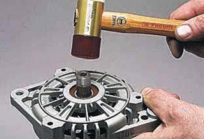
Using a hammer with a plastic head, knock the rotor shaft out of the bearing.
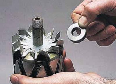
We remove the spacer sleeve from the rotor shaft..
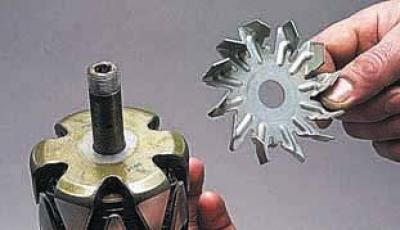
…and the fan impeller.
Using a screwdriver, we bend the ends of the rectifier block leads..
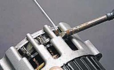
…and we unsolder the stator winding terminals from the rectifier block terminals.
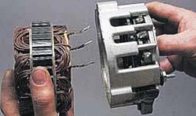
We separate the stator and the rear cover of the generator.
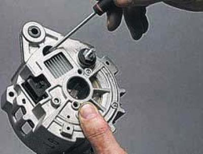
We push out two pins..
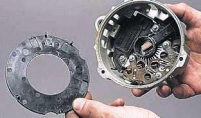
…and remove the plastic reflective washer.
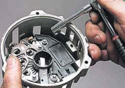
With the head "on 8" with an extension cord, we unscrew the nut for fixing the output of the "WAT" terminal (contact bolt)…
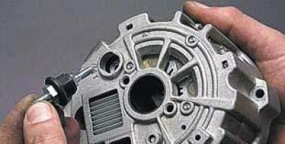
…and remove the contact bolt.
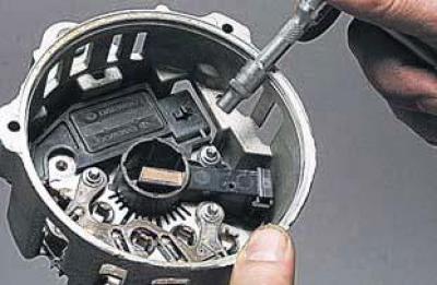
Using the E6 head with an extension, unscrew the four screws securing the rectifier unit and the brush holder with the voltage regulator and remove them from the cover.
We bend the end of the rectifier block lead..
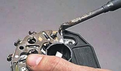
…and we unsolder the voltage regulator terminal from the rectifier block terminal.
We remove the voltage regulator.
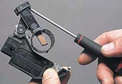
Having released three latches with a screwdriver,
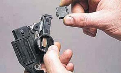
…remove the brush holder cover.
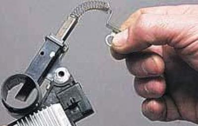
We remove the brush assembly from the brush holder.
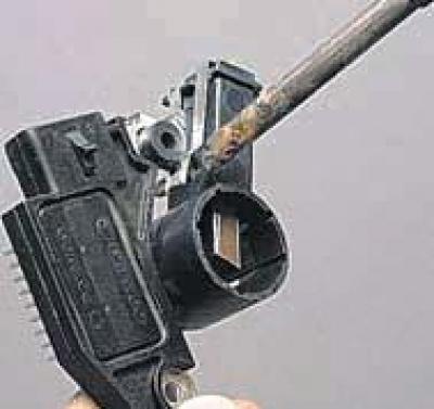
To remove the second brush, we unsolder its terminal from the terminal of the voltage regulator.
To replace the front cover bearing…
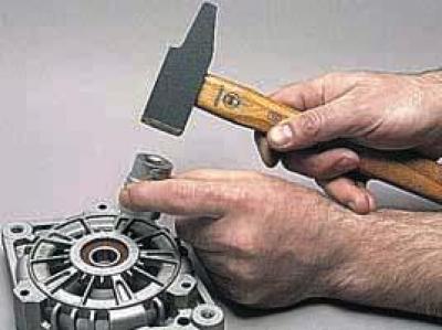
…we press out the bearing with a suitable piece of pipe or a tool head, transferring the force only to the outer ring of the bearing.
To check the rotor winding for open circuit and short circuit…
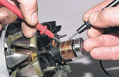
…we connect the ohmmeter probes to the contact rings.
We measure the resistance of the rotor winding, which should be within the range of 1.7–2.3 Ohms.
If the resistance is less than the specified value, then the rotor windings are short-circuited; if the resistance is very high, (tends to infinity), this means that there is a break in the rotor windings.
In both cases, the generator rotor must be replaced.
To check if the rotor windings are shorted to ground..
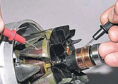
…we connect the ohmmeter probes to the rotor body and alternately to the contact rings.
The measured resistance should be very high (strive for infinity).
If the ohmmeter shows a small resistance, it means that the rotor windings are shorted to ground.
In this case, the generator rotor must be replaced.
To check the stator windings for breakage…
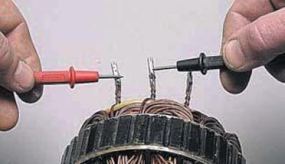
…using an ohmmeter, we measure the resistance between all the winding terminals one by one.
If the measured resistance tends to infinity, then there is a break in the stator windings and the generator stator must be replaced.
To check if the stator windings are shorted to ground..
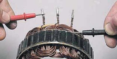
…we connect the ohmmeter probes to the stator body and to each winding terminal in turn.
The measured resistance should be very high (strive for infinity).
If the ohmmeter shows a small resistance, it means that the stator windings are shorted to ground.
In this case, the generator stator must be replaced.
To check the rectifier block…
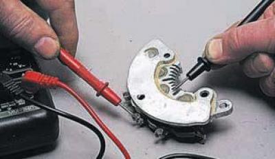
…we connect the ohmmeter probes to the terminal of the rectifier unit, which is connected to the phase winding of the stator, and to the air radiator of the diodes…
…and measure the resistance.
Then we swap the ohmmeter probes and measure the resistance again.
If the ohmmeter readings are the same in both cases, then the rectifier unit is faulty and needs to be replaced.
We check the other two diode circuits of the rectifier in the same way.
To check the diodes of the rectifier block…
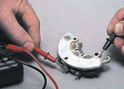
…we connect the ohmmeter probes to the terminal of the rectifier unit, which is connected to the phase winding of the stator, and to the base plate…
…and measure the resistance.
We swap the ohmmeter probes and measure the resistance again.
If the ohmmeter readings do not change, then the rectifier unit is faulty and must be replaced.
We check the other two diode circuits in the same way.
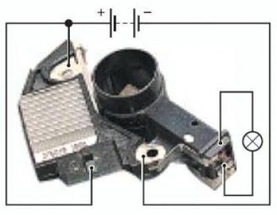
To check the voltage regulator, connect a test lamp (1–5 W, 12 V) between the brushes of the brush holder.
We apply 12 V voltage from a DC source: "+" to the "L" terminal and simultaneously to the "BAT" output of the voltage regulator, "–" to the second output of the voltage regulator.
We recommend inserting a screw into the hole of this voltage regulator terminal and tightening the nut to ensure contact between the terminals of the regulator and the brush.
The lamp should light up.
Then we apply a voltage of 15–16 V, and the lamp should go out.
If the lamp lights up in both cases, the regulator is damaged; if it does not light, there is a break in the circuit or the contact between the brushes and the terminals of the regulator is broken.
In both cases, the regulator should be replaced.
We assemble the generator in reverse order.
For ease of installation of brushes on contact rings when connecting the rear cover assembly with the stator and the front cover assembly with the rotor, we recess the brushes into the brush holder and…
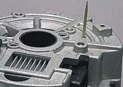
…we insert a suitable pin into the hole in the rear cover of the generator (a wooden stick or a piece of wire) and fix the brushes in the recessed position.
After assembling the generator, remove the pin.
The brushes, under the action of the springs, are displaced towards the contact rings.
After installing the generator, adjust the belt tension.