


Description of the design
The on-board network is direct current, with a nominal voltage of 12 V.
The electrical equipment is made using a single-wire circuit: the negative terminals of the power sources and consumers are connected to the "ground" - the car body and power unit, which act as the second wire.
When the engine is not running, the switched-on consumers are powered from the battery, and after the engine is started, from the generator.
When the generator is running, the battery is charged.
The car is equipped with a maintenance-free lead starter battery 6ST–55A1.
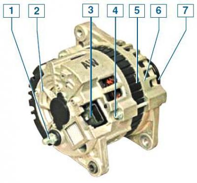
Generator: 1 – "VAT" output; 2 – back cover; 3 – connector; 4 – tension screw; 5 – stator; 6 – front cover; 7 – pulley
The generator is a synchronous AC electric machine with a built-in rectifier unit and voltage regulator.
The generator pulley is driven by a poly-V belt from the auxiliary drive pulley.
The stator and generator covers are tightened with three screws.
The rotor shaft rotates in ball bearings mounted in the generator covers.
Sealed bearings, the grease contained in them is designed for the entire service life of the generator.
The rear bearing is pressed onto the rotor shaft and installed in the cover with a small gap.
The front bearing is pressed into the front cover, and the bearing fits onto the rotor shaft as a sliding fit.
The generator stator contains a three-phase winding, made according to the "triangle" scheme.
The ends of the phase windings are soldered to the terminals of the rectifier block, consisting of six silicon diodes (valves) - three "positive" and three "negative", pressed into two horseshoe-shaped aluminum plate holders in accordance with the polarity (positive and negative on different plates).
On one of the plates there are also three additional diodes, through which the excitation winding of the generator is powered after the engine is started.
The rectifier unit is fixed to the rear cover of the generator.
The excitation winding is located on the generator rotor, and its terminals are soldered to two copper slip rings on the rotor shaft.
Power is supplied to the excitation winding through two brushes, which are installed in the brush holder.
The brush holder and voltage regulator are fixed to the rear cover of the generator.
The voltage regulator is a non-separable unit; if it fails, it is replaced.
When the ignition is turned on, voltage is supplied to the excitation winding of the generator, and the low battery indicator in the instrument cluster lights up.
After starting the engine, the excitation winding is powered by additional diodes of the rectifier unit (the alarm goes out).
If the indicator lights up after starting the engine, this indicates a malfunction of the generator or its circuits.
the "minus" of the battery must always be connected to the "ground" of the car, and the "plus" to the "BAT" terminal of the generator.
Reverse connection will cause breakdown of generator diodes.
When the generator is running, do not disconnect the battery, as the resulting voltage surges may damage the electronic components of the circuit.
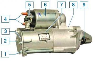
Starter: 1 – tension bolt; 2 – brush holder mounting screw; 3 – back cover; 4 – contact bolts; 5 – control output of the traction relay; 6 – traction relay; 7 – body; 8 – front cover; 9 – drive shaft
The starter is a four-brush DC electric motor with excitation from permanent magnets, with a planetary gearbox, a freewheel roller clutch and a two-winding traction relay.
Permanent magnets are attached to the steel body of the starter.
The starter housing and covers are tightened with two bolts.
The armature shaft rotates in plain bearings.
The torque from the anchor shaft is transmitted to the drive shaft through a planetary gearbox consisting of a central and crown gear (with internal gearing) gears and three satellites on the carrier (drive shaft).
A freewheel clutch is installed on the drive shaft (overrunning clutch) with drive gear.
The traction relay is used to engage the drive gear with the flywheel ring gear of the engine crankshaft and turn on the power supply to the starter electric motor.
When the ignition key is turned to the "START" position, voltage is supplied to both windings of the traction relay (retracting and retaining).
The relay anchor is pulled in and moves the drive lever, which moves the freewheel clutch with the drive gear along the splines of the drive shaft, bringing the gear into engagement with the flywheel ring gear.
In this case, the pull-in winding is switched off and the contacts of the traction relay are closed, turning on the starter electric motor.
After the key is returned to the "ON" position, the holding winding of the traction relay is de-energized, and the relay armature, under the action of the spring, returns to its original position - the relay contacts open, and the drive gear disengages from the flywheel.
The faulty traction relay is replaced.
A starter drive malfunction is detected during inspection after disassembling the starter.
The lighting and signaling system includes two headlights; fog lights; side direction indicators; rear lights; license plate lights; additional brake signal; interior and luggage compartment lighting lamps; sound signal.
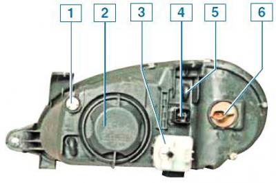
Headlight: 1 — screw for adjusting the headlight beam in the horizontal plane; 2 — cover for high/low beam and parking light lamps; 3 — headlight beam direction regulator motor-reducer; 4 - electrical connector; 5 - ventilation valve; 6 — direction indicator lamp socket
The headlight unit contains: a dual-filament halogen high/low beam lamp, a side light lamp, and a turn signal lamp (orange color) and the actuator (gear motor) headlight beam direction regulator.
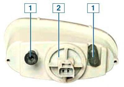
Fog light: 1 - headlight beam adjustment screw; 2 - headlight lamp cover; 3 - ventilation valve
Fog lights are installed in the front bumper.
The fog light contains a halogen lamp, the direction of the light beam of which is adjusted with a screw.
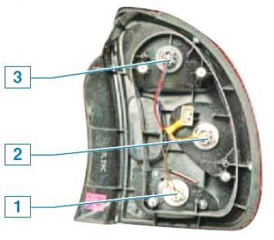
Location of lamps in the rear light: 1 - fog light; 2 - direction indicators; 3 - brake light and parking light
The rear light contains the following lamps: brake light and side light; direction indicator; fog light (in the left lamp); reversing light (in the right lantern).
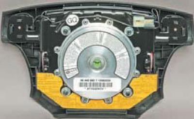
The car is equipped with a driver's airbag, which is located on the steering wheel.
The airbag control unit is located in the vehicle interior under the instrument panel console.
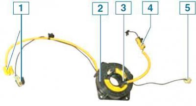
Drum device with spiral cable: 1 - pads for connection to the instrument panel wiring harness; 2 — drum device body; 3 - drum device leash; 4 - Airbag wiring harness; 5 — horn switch wiring block
To electrically connect the airbag and horn switches to the instrument panel wiring harness instead of the usual sliding contact (to avoid sparking and unintentional deployment of the airbag) a drum device with a spiral cable, operating on the principle of a tape measure, was used.
The drum device is attached to the steering column paddle connector.
Several turns of metal-plastic tape, which is an electrical conductor, are spirally laid in the cylindrical plastic body of the device.
One end of the tape is connected to the instrument panel wiring harness through wires with pads.
The other end of the tape is brought out to the protruding leash of the drum and connected by wires to the pads with the airbag and the horn switches.
The drum leash enters the hole in the steering wheel hub.
When rotating, the wheel turns the drum by the leash, and with it the tape, which is located in the cylindrical body either at a larger or smaller radius.
From its center position, the drum can rotate in each direction until it stops by 3.75 turns.
This prevents the tape from breaking when turning the steering wheel from neutral to full lock in each direction.
Before installing the steering wheel, it is necessary to set the drum of the device to the middle position, while the leash should be located on top.
All door locks are locked by electric drives.
Removal of electric door lock drives is shown in Chapter. Body.
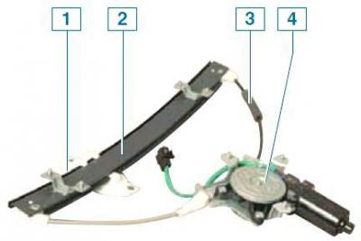
Electric window: 1 - slider; 2 - guide; 3 — cable; 4 — gear motor
Depending on the configuration, the car may be equipped with electric windows in front of the doors.
Removal of electric windows is shown in Chapter. Body.
The window lift motor-reducer consists of a worm gear and a reversible DC electric motor.
A drum with a cable is installed on the output shaft of the gearbox.
A slider is attached to the cable and moves along the guide.
Glass holders are attached to the slider with two self-tapping screws.
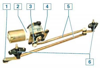
Windshield Cleaner: 1 — shaft lever; 2 — gear motor; 3 - crank; 4 — bracket; 5 - traction; 6 — shaft support
The windshield wiper is installed under the windshield trim.
The wiper motor-reducer is mounted in the engine compartment on the front panel.
The cleaner's electric motor is three-brush, two-speed, with excitation from permanent magnets.
The windshield washer consists of a polyethylene tank with an electric pump, nozzles on the hood and connecting hoses.
The washer reservoir is located behind the left front fender.
The filler neck of the tank is located in the engine compartment.
Most electrical circuits are protected by fuses.
Powerful consumers (rear window heating element, engine cooling fan, electric windows and others) are connected via a relay.
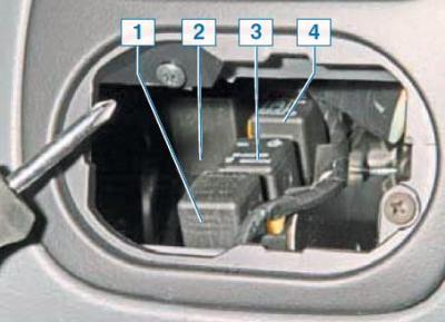
Location of the relay in the instrument panel: 1 — relay for switching on the fog light in the left rear light; 2 — relay of the fourth speed of the electric motor of the heater fan; 3 — intermittent windshield wiper relay; 4 — direction indicator and hazard warning light relay
The fuses and most of the relays are installed in two mounting blocks, one of which is located on the left, in the engine compartment, and the second is in the passenger compartment, under the left side trim.
Four relays are installed in the instrument panel, behind the headlight beam direction adjuster.
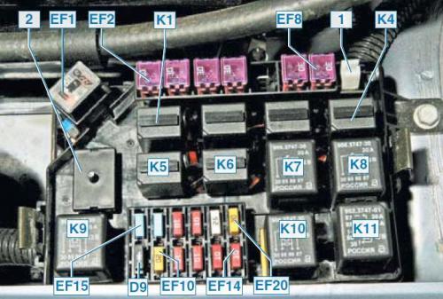
Engine compartment fuse and relay box: EF1-EF20 - fuses; K1-K6 - small size relays; K7-K11 - large size relay; 1 - tweezers for extracting small fuses and relays; 2 - jumper block
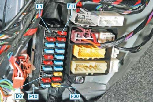
Fuse box mounting in the car interior