


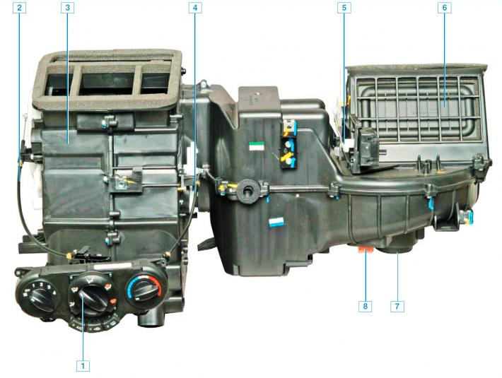
Heater with control unit for heating, ventilation and air conditioning: 1 - Heating, ventilation and air conditioning control unit; 2 — distribution valve rod; 3 — heater; 4 — temperature regulator flap rod; 5 — recirculation flap drive; 6 — air recirculation flap; 7 — fan electric motor; 8 — electronic fan motor speed controller.
The car can be equipped with either a heating and ventilation system or a heating, ventilation and air conditioning system, which serve to create the most comfortable conditions for the driver and passengers, regardless of weather conditions.
The heating and ventilation system includes: a heater, a heater fan, air ducts and deflectors. The air ducts supply air from the heater to the windshield and side window deflector grilles, to the central and side deflectors on the instrument panel, and to the ventilation openings in the heater casing to supply air to the driver's and passengers' feet. The system is controlled by turning the handles located on the heating, ventilation and air conditioning control unit. The control unit is installed on the instrument panel console.
The heater is installed under the instrument panel on the right, the air ducts are fixed under the instrument panel. The heater housing contains: heater fan; electronic fan motor speed controller; distribution dampers that direct air flows to specific areas; heater radiator (connected by hoses to the engine cooling system), through which the coolant constantly circulates. Depending on the position of the valve associated with the temperature regulator, the outside air can pass through the heater radiator or bypass it.
The air is heated by the heat of the engine coolant circulating through the heater radiator tubes. For example, at an outside temperature of –18°C, the air after passing through the heater radiator heats up to 54°C, at –4°C — accordingly, up to 59°C, at 10°C — up to 64°C, at 24°C — up to 68°C.
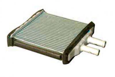
Heater radiator
When the car is moving, air enters the heater through the grilles located in front of the windshield. The heater fan serves to increase the air supply to the passenger compartment while the car is moving, as well as when parked.
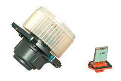
Heater fan and electronic speed controller of the heater fan electric motor
The intensity of air supply is determined by the fan speed. The fan motor can rotate at four different speeds.
The distribution of air flows in the cabin is carried out by the air flow distribution regulator, which is connected to the flaps by rods.
By controlling the flaps, the regulator directs air flows through the air ducts to the central and side deflectors, to the lower ventilation openings in the heater casing, as well as to the glass defroster grilles located in the instrument panel.
Air from the passenger compartment exits through valves installed behind the sides of the rear bumper.
To speed up the heating of the passenger compartment and prevent outside air from entering the passenger compartment (when driving a car on smoky, dusty sections of the road) serves as an air recirculation system. When you press the air recirculation mode button, the recirculation system flap closes off the outside air from entering the car's interior and the air in the interior begins to circulate in a closed circuit without exchanging with the outside air. At the same time, the indicator in the button lights up.
Some cars are equipped with an air conditioning system. The air conditioning system is designed to reduce the temperature and humidity of the air in the passenger compartment. The air conditioner is turned on by pressing the air conditioner switch button located in the heating, ventilation and air conditioning control unit, while the heater fan must be on. When the air conditioner is turned on, the indicator located in the air conditioner switch button lights up.
The air conditioner compressor is mounted on the engine bracket at the front, under the power steering pump. The compressor is driven by a poly V-belt from the auxiliary drive pulley. The compressor pulley has a built-in electromagnetic clutch that switches the compressor shaft on and off the pulley based on ECU signals.
After the compressor, the refrigerant vapor enters the condenser, located in front of the engine cooling system radiator.
Next, the refrigerant enters the receiver, which is attached to the condenser on the right side.
From the receiver, the refrigerant enters the reducer and then the evaporator, located under the instrument panel in the heater body.
The air cooled in this way enters the car's interior. From the evaporator, the refrigerant is sucked in again by the compressor, and the working cycle is repeated. Valves for filling and releasing the refrigerant from the air conditioning system are installed on the high-pressure and low-pressure pipelines. A refrigerant pressure sensor is installed on the high-pressure pipeline.
The pressure sensor sends a signal to the ECU, which controls the electric fan of the engine cooling system depending on the refrigerant pressure and the vehicle speed. In addition, based on the pressure sensor signals, the ECU switches off the air conditioning compressor if the refrigerant pressure in the system is too low or too high.
A shut-off valve is installed in the pipe fitting under the pressure sensor, which closes when the sensor is unscrewed. Therefore, when replacing the pressure sensor, there is no leakage of refrigerant from the air conditioning system.
The refrigerant in the air conditioning system is under high pressure. When working on depressurizing the air conditioning system, avoid getting it in your eyes, on your skin, or inhaling it. Any work with the refrigerant should only be done in a ventilated area. When filling the air conditioning system, use only materials recommended by the manufacturer. Do not weld or solder on the air conditioning system components. Repair and maintenance work on the air conditioning system should be done at specialized service centers. Special equipment is used to search for leaks in the system, and a special contrast agent is introduced into the system, allowing even minor leaks to be detected. After removing the refrigerant, it is imperative to pump air out of the system to remove any remaining moisture.
Before filling the system, it is necessary to add a special oil recommended by the manufacturer.
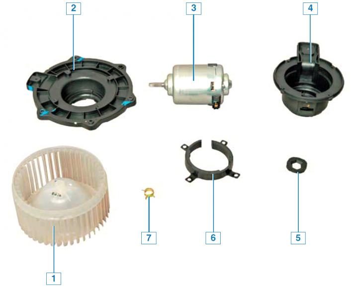
Heater Fan Parts: 1 — impeller; 2 — base; 3 - fan electric motor; 4 — electric motor casing; 5 - Electric motor lining; 6 - Electric motor holder; 7 — clamp.
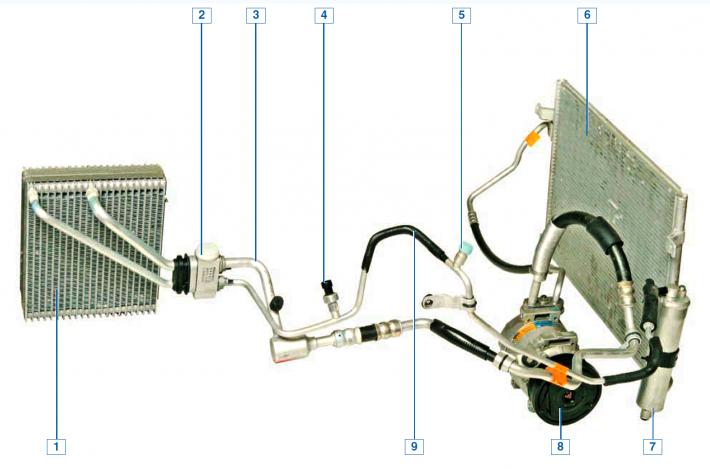
Air conditioning system: 1 - evaporator; 2 — gearbox; 3 - low pressure pipeline; 4 - refrigerant pressure sensor; 5 - valve for filling and releasing refrigerant; 6 - capacitor; 7 — receiver; 8 — compressor; 9 - high pressure pipeline.
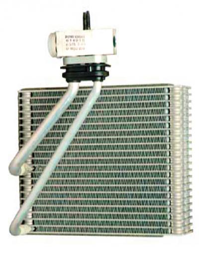
Air conditioner evaporator.

Air conditioner receiver.
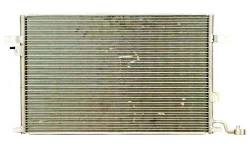
Air conditioner condenser.