


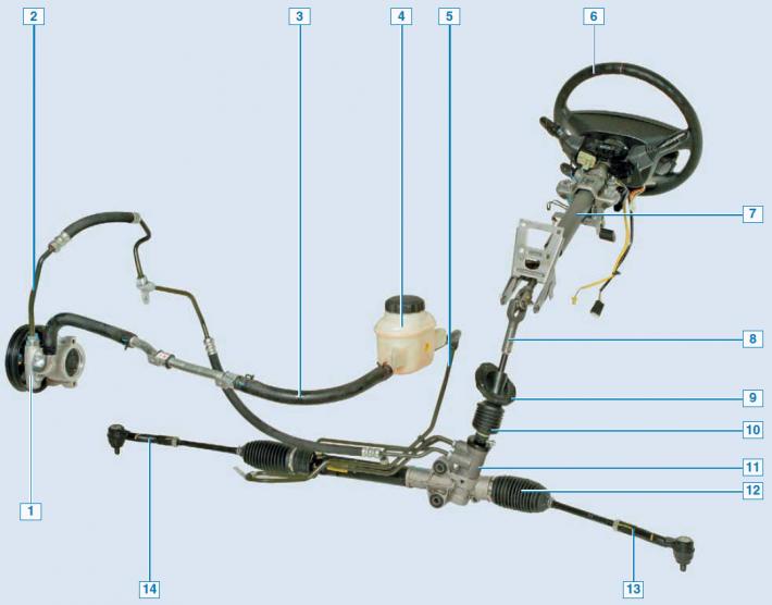
Steering elements: 1 — power steering pump; 2 — discharge line; 3 - filling line; 4 — power steering fluid reservoir; 5 - drain line; 6 - steering wheel; 7 - steering column; 8 — intermediate steering shaft; 9 — intermediate shaft seal; 10 — joint boot; 11 - steering mechanism; 12 — steering gear cover; 13 - left steering rod; 14 - right steering rod.
The vehicle's steering system consists of a steering wheel with an airbag built into it, a safety steering column, an intermediate shaft, a steering gear with rods and tips, a pump and a power steering reservoir with pipelines.
The steering column is attached to the front panel with two nuts (top) and two bolts (bottom), and to the instrument panel frame with two nuts.
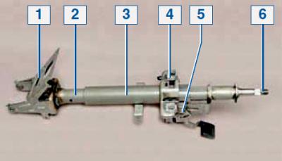
Steering column: 1 — bracket for mounting the column to the front panel; 2 - inner tube; 3 - outer pipe; 4 — bracket for mounting the column to the instrument panel frame; 5 — column tilt adjustment mechanism; 6 — steering shaft.
The steering wheel is mounted on the splines of the steering shaft, located in the column, and secured with a central nut.
The steering shaft, through an intermediate shaft with two cardan joints, is connected to the steering gear shaft-pinion.
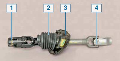
Intermediate shaft: 1 - lower cardan joint; 2 — anther; 3 - seal; 4 - upper cardan joint.
The design of the intermediate steering shaft allows for changes (shorten) its length during a car collision.
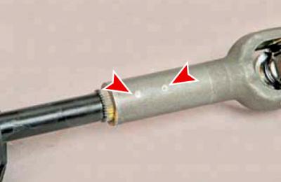
In the event of an accident, two plastic pins connecting the shaft parts are cut off.
The steering gear is of the "pinion-rack" type. The mechanism housing is attached to the front suspension subframe with a bolt and stud (with a nut) passing through rubber-metal bushings inserted into the housing holes, and the housing pipe is fastened with a bracket through a rubber cushion. The steering rod joint housings are screwed into the threaded holes of the rack ends. The tips are screwed onto the outer threaded ends of the steering rods, the ball joints of which are connected to the steering knuckles of the steered wheels.
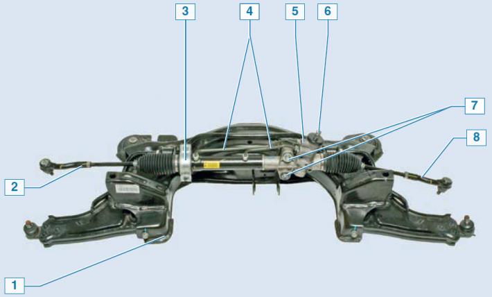
Steering gear assembly with front suspension subframe: 1 — subframe; 2 — right steering rod end; 3 — crankcase pipe mounting bracket; 4 - connecting pipes of the power steering; 5 — mechanism housing; 6 — gear shaft; 7 — bolt and nut with stud for fastening the crankcase; 8 — left steering rod end.
The length of the steering rod assembly with the tip is changed by rotating the rod with the lock nut loosened. This allows you to adjust the toe-in of the vehicle's steered wheels.
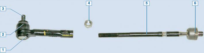
Tie rod with tip: 1 — tip; 2 — anther; 3 — ball joint pin of the tip; 4 — lock nut; 5 - traction; 6 — traction joint.
The ball joints of the tie rod end and the tie rod itself are of a non-separable design and do not require replenishment of the lubricant stored inside for their entire service life.
The power steering is built into the steering gear.
The hydraulic booster system also includes: a tank, a vane pump, drain, pressure and filling pipes.
The power steering fluid reserve is located in a tank located in the engine compartment and secured to the wall of the battery shelf. To control the fluid level, MIN and MAX marks are applied to the translucent tank body.
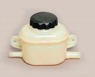
Power steering fluid reservoir.
The power steering pump is mounted on a common bracket of the engine cylinder block, to which the tension roller of the auxiliary drive belt and the air conditioning compressor are also mounted. The pump pulley is driven by a poly V-belt from the engine crankshaft pulley.
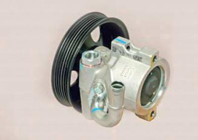
Power steering pump.
The working fluid is drawn from the tank by a pump and supplied under high pressure to the distribution device (distributor), located in the steering gear housing and mechanically connected to the steering shaft.
The hydraulic cylinder piston is fixed to the steering gear rack. When the steering wheel is turned, the distributor connects one of the hydraulic cylinder chambers to the pump discharge line, and the other chamber to the drain line.
In this case, the hydraulic cylinder piston, due to the difference in pressure of the working fluid, moves the rack to the left or right and through the steering rods and the levers of the steering knuckles turns the steered wheels of the car. If the hydraulic booster fails, the ability to control the car is preserved, but the force on the steering wheel increases.
Some vehicles use a power steering system that provides variable power assistance depending on the vehicle speed.
At low speeds, the system provides maximum assistance to make turning and parking easier.
At high speeds, the steering assist is reduced to improve the vehicle's directional stability. The system accomplishes this by varying the fluid flow through the pump. Electronic Steering Control Unit (fixed to the dashboard bracket, under the glove compartment) receives signals: about the vehicle speed - from the engine control unit; about steering wheel angle (to calculate the angular velocity of the steering wheel) — from a sensor located at the bottom of the steering shaft. After processing the signals, the unit sends a control signal to the electromagnetic needle valve of the pump, which regulates the flow of the working fluid through the pump.
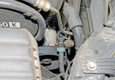
Location of the solenoid valve of the power steering pump.