


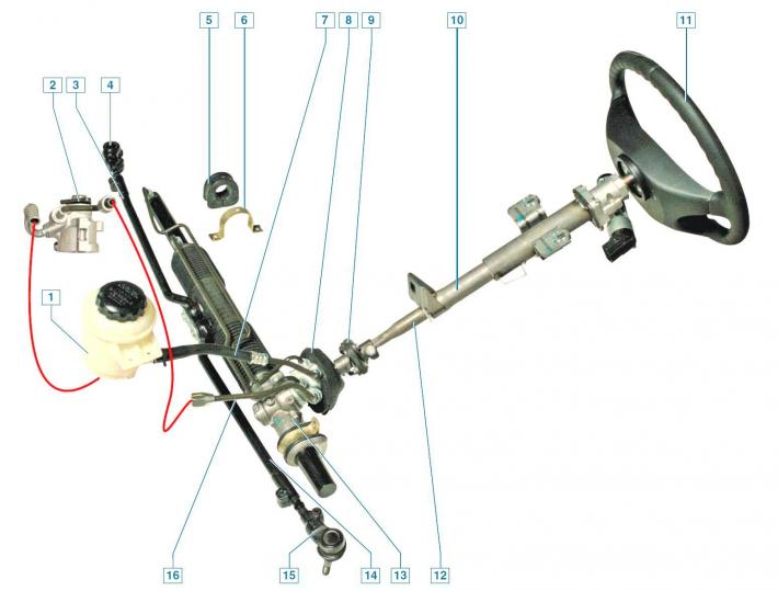
Power steering components: 1 — power steering fluid reservoir; 2 — power steering pump; 3 - inner tip of the right steering rod; 4 — outer end of the right steering rod; 5 - right support of the steering gear; 6 — steering gear support bracket; 7 — drain line hose; 8 — steering gear seal; 9 - elastic coupling; 10 - steering column; 11 - steering wheel; 12 — steering shaft; 13 - steering mechanism; 14 — inner tip of left steering rod; 15 — outer tip of left steering rod; 16 — discharge line
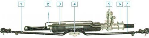
Steering gear with rods assembled: 1 – right steering rod; 2 – connecting pipes of the power steering; 3 – protective cover; 4 – locking plate for steering rod mounting bolts; 5 – gear shaft; 6 – steering gear housing; 7 – left steering rod
The vehicle's steering system has a trauma-safe steering column, which prevents the steering wheel from moving towards the driver when the steering mechanism is displaced rearward during a frontal collision.
This is ensured by the design of the steering column, which consists of two metal tubes.
The lower inner pipe is installed in the outer pipe through plastic split rings, ensuring their tight connection.
However, when shock loads are exceeded, for example, when a car collides with an obstacle, the connection of the pipes allows them to move relative to each other.
The design of the steering shaft also allows for changes (shorten) its length in a vehicle collision as a result of the shearing of two plastic pins connecting the two parts of the shaft.
The rack-and-pinion steering mechanism is secured in the engine compartment on the front body panel with two brackets through rubber mounts.
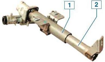
Steering column: 1 - Upper outer pipe; 2 - lower inner tube
The steering gear housing is cast from aluminum alloy.
The drive gear, made integral with the shaft, is mounted on bearings in the steering gear housing (shaft-gear), which is engaged with the rack.
The rack is pressed against the gear by a spring through a stop, which is sealed in the crankcase by a rubber ring.
The spring rests against the adjustment plug.
The adjusting plug is held from loosening by a lock nut.
The steering rods are attached to the rack with bolts that pass through the support plate, the rubber-metal hinges of the inner ends and the rack slider.
The bolts are secured from loosening by a locking plate placed on the bolt heads.
The steering gear consists of two steering rods connected by ball joints to pivot arms welded to the shock absorber struts of the front suspension.
Each rod consists of an inner end, an outer end and an adjusting screw.
The ends of the adjusting screw have external threads in the opposite direction (right and left), there is a hexagon socket in the middle of the screw for a key.
The length of the steering rod is changed by turning the adjusting screw, which is screwed into the threaded holes of the inner and outer ends, with the tightening of the bolts of the terminal connections of the ends loosened.
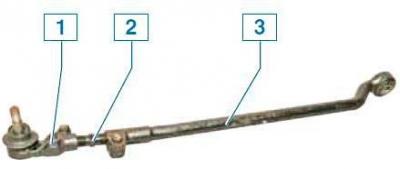
Left steering rod: 1 - outer tip with ball joint; 2 - adjusting screw; 3 - inner tip
This allows you to adjust the toe-in of the vehicle's steering wheels.
After completing the adjustment, the terminal connections of the steering rod ends are tightened with bolts.
The ball joint of the outer tie rod end has a non-separable design and does not require replenishment of the supply of grease placed inside for its entire service life.
The outer and inner ends of the right and left steering rods are not interchangeable.
The steering column shaft is attached to the steering gear drive pinion via an elastic coupling.
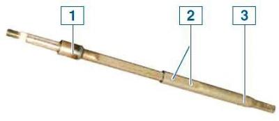
Steering shaft: 1 - upper part of the shaft; 2 - plastic pins; 3 - lower part of the shaft
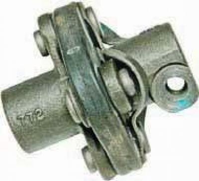
Flexible coupling
The steering wheel is mounted on the splines at the top of the shaft and secured with a nut.
The steering column is attached to the front shield brackets: at the front - with one nut, at the rear - with two nuts.
The power steering is built into the steering gear.
The hydraulic booster system includes: a vane pump, a reservoir for the working fluid, drain and pressure lines.
The pump is bolted to the engine cylinder block on the right side and is driven by a belt from the engine crankshaft pulley.
The working fluid from the tank is supplied by a pump under high pressure to the distribution device (distributor), located in the steering gear housing and mechanically connected to the steering shaft.
The hydraulic cylinder piston is attached to the steering gear rack.
When the steering wheel is turned, the distribution device connects one of the hydraulic cylinder chambers to the pump discharge line, and the other chamber to the drain.
In this case, the piston of the hydraulic cylinder, due to the difference in pressure of the working fluid, moves the rack to the left or right and, through the steering rods and steering levers, turns the steered wheels of the car.
If the hydraulic booster fails, the ability to control the vehicle is retained, but the effort required to turn the steering wheel increases.
The power steering reservoir is installed in the engine compartment on a bracket welded to the left mudguard cup.
To control the liquid level, MIN and MAX marks are applied to the translucent body of the tank.
The original article is on the website: ChevyMan.ru