


Disconnect the wire terminal from the negative terminal of the battery.
Remove the steering wheel (see Removal the steering wheel).
Remove the steering column switches and connector (see Removal the steering column paddle shifters, coil cable drum and switch connector).
To gain access to the nuts securing the front and rear steering column brackets, remove the lower instrument panel trim (see Removal the instrument panel).
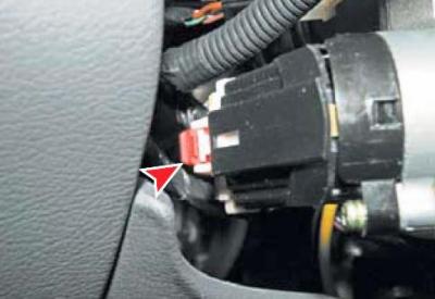
By pressing the block lock, we disconnect the block of wires from the ignition switch.
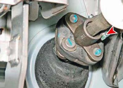
Using a 12 mm head, unscrew the bolt of the terminal connection of the elastic coupling flange with the steering column shaft and remove the bolt.
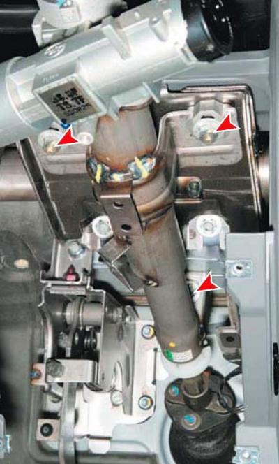
Using a 12 mm head, unscrew the two nuts securing the rear bracket and using a high 12 mm head, unscrew the nut securing the front steering column bracket to the front shield brackets.
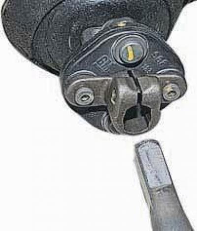
We remove the shaft from the hole in the coupling flange (for clarity, shown on removed units)…
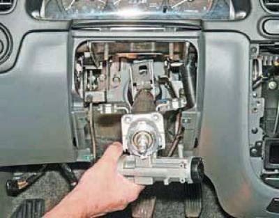
…and remove the steering column assembly.
To remove the steering shaft from the steering column housing, insert the key into the ignition switch and turn it from the LOCK position to the ACC position, unlocking the locking device.
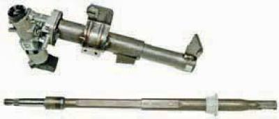
We remove the steering shaft with the centering sleeve from the steering column housing.
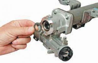
We remove the thrust bearing ring from the column housing.
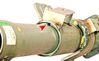
The lower tube of the steering column is connected to the upper tube through a split plastic ring.
This ring cannot be removed - it serves to ensure the possibility of folding the steering column in the event of an emergency collision of the car.
When installing, insert the shaft into the steering column (unlocking the ignition locking device), we put a split centering sleeve on the shaft..
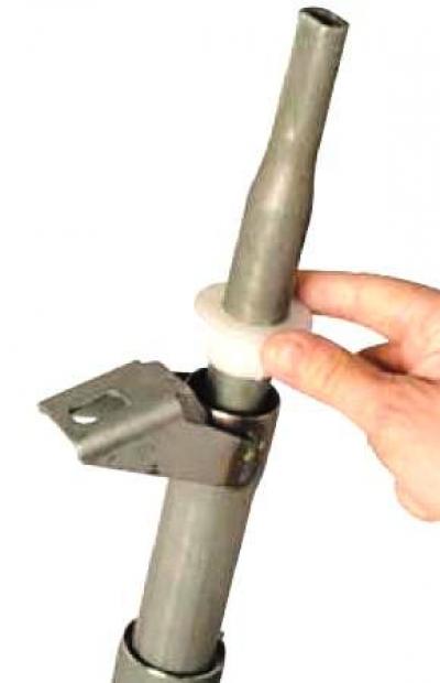
…and, having moved it along the shaft, we insert it into the steering column tube.
We insert the shaft tail into the hole in the elastic coupling flange so that the chamfer on the shaft aligns with the hole for the tie bolt, and screw in the tie bolt without tightening it.
After tightening the nuts securing the front and rear brackets of the steering column, move the shaft up until it stops in the bearing and, holding it in this position, tighten the clamping bolt of the terminal connection of the elastic coupling flange.
Further installation of the steering column and instrument panel parts is carried out in the reverse order.
(The article is based on data from the website: ChevyMan)