


Use a puller to remove the ball joints from the lever sockets.
Loosen the bracket mounting bolts to the body side member and remove the bracket. Secure the bracket in a vice, remove the cap 1 (figure 5-6), unscrew nuts 2, then remove washer 3, spacer ring 7 and pendulum lever 8.
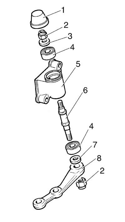
Figure 5-6. Pendulum arm parts with bracket:
1 - bracket cap;
2 - self-locking nut;
3 - upper washer;
4 - bearing;
5 - bracket;
6 - pendulum lever axis;
7 - distance ring;
8 - pendulum lever.
Press out axle 6 with lower bearing 4 from bracket 5, then press out the upper bearing. Remove the lower bearing from axle 6.
Assembly and installation. The order of assembly of the pendulum arm bracket is the reverse of disassembly. It is recommended to replace bearings 4 with new ones.
After securing the bracket to the side member with bolts, self-locking nuts and flat washers, tighten them with a torque wrench.
Connect the ball joints of the rods to the pendulum arm.