


Removal and installation
Removal. Unscrew the cotter pins and nuts that secure the ball joints of the side rods to the levers 9 (see figure 5-1) on the steering knuckles 7.
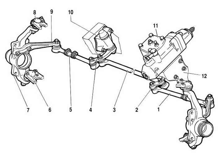
Figure 5-1. Steering gear assembly with drive:
1 - side pull;
2 - bipod;
3 - medium thrust;
4 - pendulum lever;
5 - adjusting coupling;
6 - lower suspension ball joint;
7 - right steering knuckle;
8 - Upper ball joint of suspension;
9 - right steering knuckle lever;
10 - pendulum arm bracket;
11 - steering mechanism;
12 - body side member.
Use a puller to remove the ball joints from the conical sockets on the levers.
Remove the cotter pins and unscrew the nuts securing the ball joints of the middle and side rods to the steering knuckle 2 and to the pendulum lever 4. Using a puller, remove the pins from the corresponding sockets on the levers and remove the rods.
Installation. Install the steering rods in the reverse order of removal. Tighten all the ball joint nuts with a torque wrench and then cotter pin them. If the nut cutout does not match the hole for the cotter pin, turn the nut by an angle less than 60° to ensure cotter pinning.
After installation, adjust the front wheel alignment.
Check and repair. Check the condition of the protective caps 2 (figure 5-5), as described above (see "Inspection, testing and adjustment of steering"). Replace damaged protective caps.
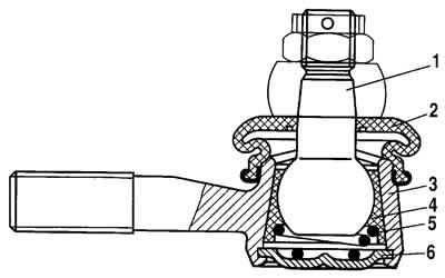
Figure 5-5. Cross-section of the tie rod ball joint:
1 - ball pin;
2 - mudguard cap;
3 - hinge housing;
4 - insert;
5 - spring;
6 - plug.
Check the condition of the ball joints of the rods for radial and axial clearance. If you feel free movement of pin 1 in housing 3, or if dirt or sand gets into the joint, or if corrosion appears on the ball joint, or if the travel of the support insert is fully used, replace the joint with the rod end.