


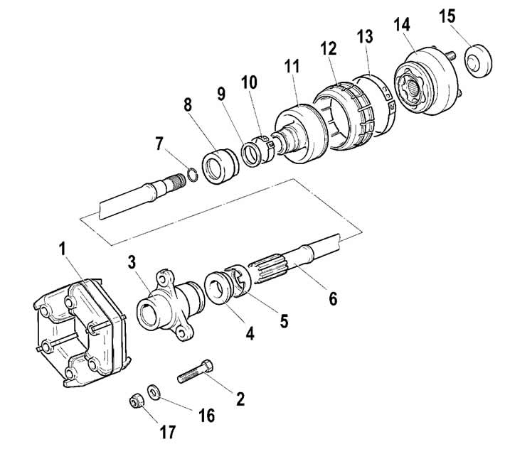
Figure 3-43. Intermediate propeller shaft parts:
1 - elastic coupling with clamp A.70025;
2 - bolt;
3 - sliding flange;
4 - flange seal;
5 - oil seal cage;
6 - intermediate shaft;
7 - retaining ring;
8 - valve casing;
9 - hinge boot valve;
10 - clamp;
11 - hinge cover;
12 - hinge boot casing;
13 - clamp;
14 - constant velocity joint;
15 - plug;
16 - balancing washer;
17 - self-locking nut.
If the joint boot is damaged, when it is necessary to check the condition of the joint parts and the quality of the lubricant, having marked the position of the joint relative to shaft 6, remove and disassemble the joint using the techniques described in subsection "Front wheel drive". When assembling the constant velocity joint, apply 20 cm² of Esma grease.
Front and rear shafts. Apply marks (with paint or a center punch), determining the relative position of the mating parts in order to connect them during assembly in the same position to maintain shaft balancing.
Install the front (rear) propeller shaft in a vice with aluminum pads. Remove the retaining rings 3 (figure 3-44), using round-nose pliers.
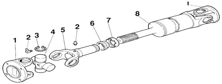
Figure 3-44. Front propeller shaft parts:
1 – cardan joint flange fork;
2 – grease nipple (not available in the variant);
3 – retaining ring;
4 – crosspiece assembly;
5 – sliding fork;
6 – oil seal;
7 – oil seal cage;
8 – cardan shaft.
Press out the bearing housings from the hinge forks, for which:
- install the cardan shaft of one of the cardan joint forks on support 1 (figure 3-45) press. Through the special bushing 2, use the press rod to move the other fork (pos. 3) of the hinge down until it stops against the crosspiece;
- having turned the hinge fork by 1800, repeat the above operations, i.e. move the other end of the fork down until it stops in the crosspiece. When performing these operations, the opposite bearing of the crosspiece will partially come out of the fork hole and it will be possible to install the bushing 1 in the resulting gap between the fork and the crosspiece (figure 3-46) with a side cutout for further complete disassembly of the bearing;
- having installed bushing 1 on the crosspiece tenon, move the hinge fork down until the bearing is pressed out;
- using the above techniques, press out the other crosspiece bearings.
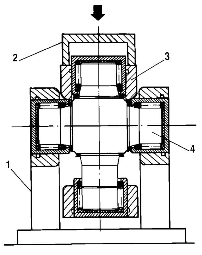
Figure 3-45. Disassembling the cardan joint:
1 - press support;
2 - bushing;
3 - hinge fork;
4 - crosspiece.
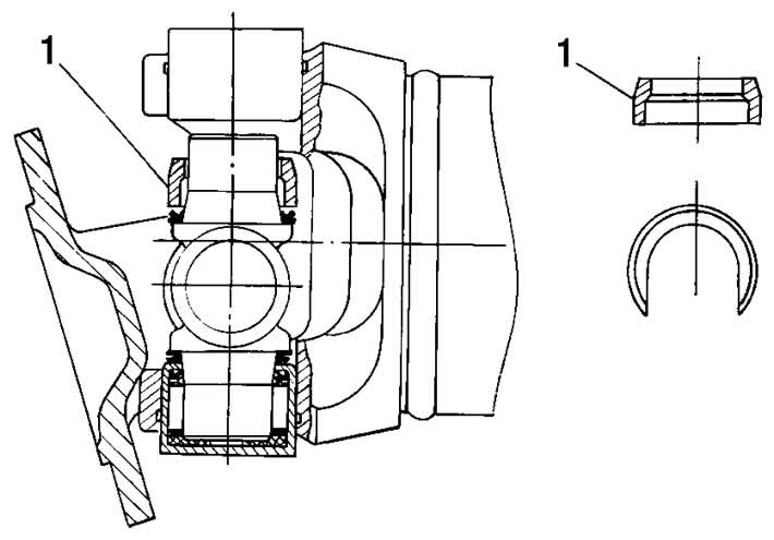
Figure 3-46. Installing the sleeve for disassembling the universal joint:
1 - bushing.
Note: Some vehicles are equipped with front and rear cardan shafts manufactured by "TIRSAN KARDAN A.S." (Türkiye), which cannot be disassembled and repaired due to the fact that they are supplied as spare parts only as an assembled unit.
Note: Some vehicles are equipped with front and rear cardan shafts with constant velocity joints. Disassemble and assemble the joints using the techniques described in Chapter "Front wheel drive".