


Necessary equipment
- J-45053 Universal Clamp Press
- DT-47599 Anchor Bolt Wrench
- J-45161 Manual Shift Shaft Bearing Replacement Puller
- J-45000 Seal Puller
Disassembly procedure
1. Remove the gearbox assembly from the vehicle. See "Gearbox with final drive assembly" in this section.
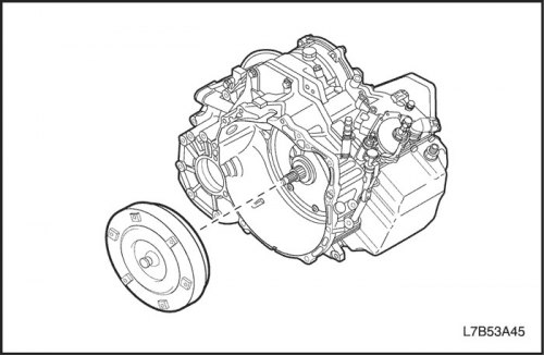
2. Remove the torque converter.
- Remove the torque converter from the gearbox with the final drive assembly.
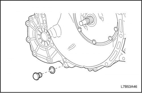
3. Remove the drain plug.
- Unscrew the drain plug and drain the automatic transmission fluid.
- Remove the gasket from the drain plug.
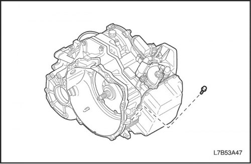
4. Remove the oil level sensor.
- Unscrew 1 bolt and remove the oil level sensor.
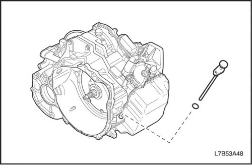
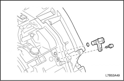
5. Remove the secondary shaft speed sensor.
- Remove 1 bolt and pull out the secondary shaft speed sensor.
Important: Be careful not to damage the secondary shaft speed sensor and the transaxle housing.

6. Remove the input shaft speed sensor and the automatic transmission range switch.
- Remove 1 bolt and pull out the input shaft speed sensor.
Important: Be careful not to damage the input shaft speed sensor and the transaxle housing.

- Use a screwdriver to press the lock washer.
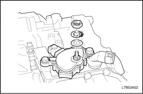
- Remove the nut and lock washer.
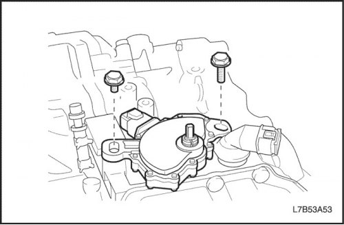
- Unscrew 2 bolts and pull out the automatic transmission range switch.
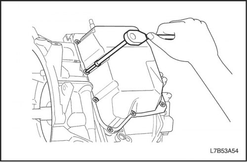
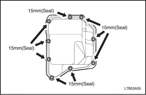
7. Remove the rear cover of the gearbox housing with the final drive assembly.
- Remove 9 Torx bolts and remove the rear cover of the gearbox housing with the final drive assembly.
Important: Care must be taken not to damage the rear crankcase cover of the main transmission assembly and the main transmission housing assembly.
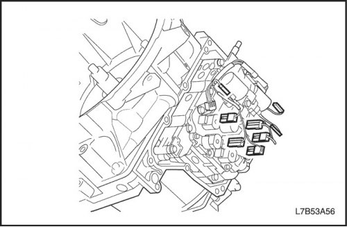
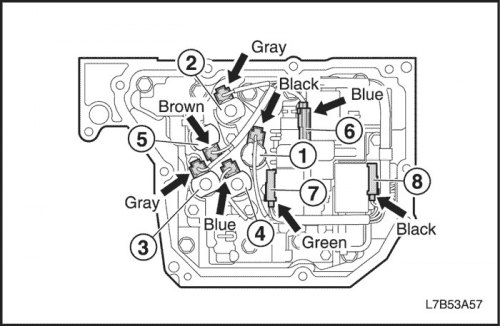
8. Disconnect the transmission wire connectors with the final drive assembly.
- Disconnect the 8 wire solenoid valve connectors.
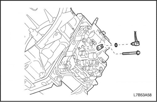
- Unscrew 1 bolt and remove the clamp, pull out the gearbox fluid temperature sensor.
Important: Be careful not to damage the connector.
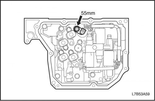
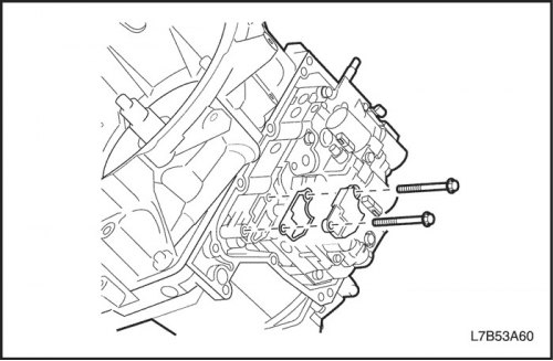
9. Remove the valve body.
- Remove 2 bolts, cover from the suction side and gasket.
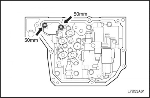
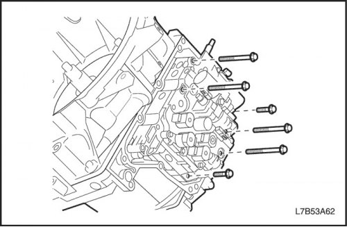
- Remove 6 bolts.
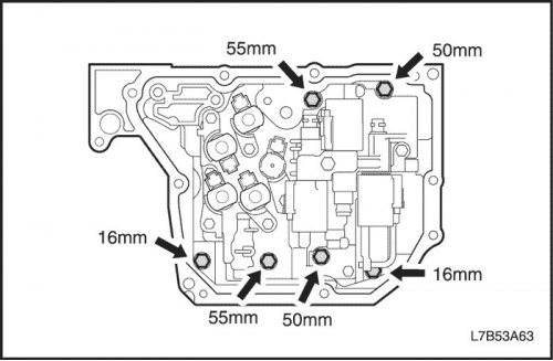
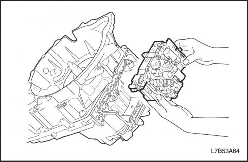
- While holding the valve block assembly, disconnect the range select valve connecting rod from the range select valve lever and remove the valve block assembly.
Important: The gear shift position is "N".
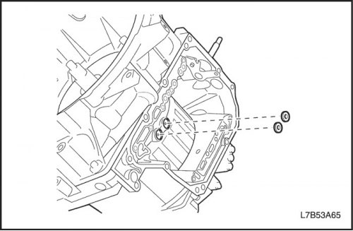
10. Remove the gasket.
- Remove 2 gaskets.
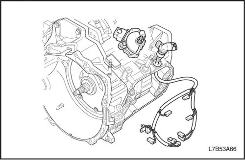
11. Remove the switch and sensor assembly from the gearbox housing with the final drive assembly.
- Remove the gearbox wire with the final drive assembly from the clamps.
- Push the solenoid valve wire out from the inside and remove it.
Important: Be careful not to damage the wiring connector and the transmission fluid temperature sensor.
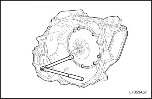
12. Remove the oil pump assembly.
- Remove 8 bolts.
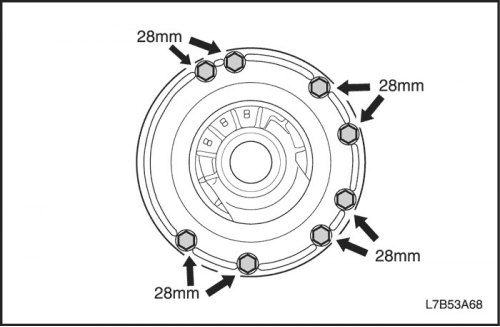
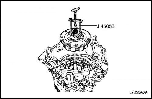
- Pull the oil pump assembly out of the transaxle case using J-45053.
Important: Care must be taken not to damage the reactor shaft sleeve.
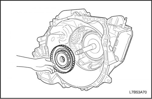
13. Remove the 2nd gear overrun brake (B1), 2nd gear brake (B2) and overrunning clutch No.1 assembly (F1).
- Remove the hub and washer of the 2nd gear overrun brake (B1) and 2nd gear brake (B2).
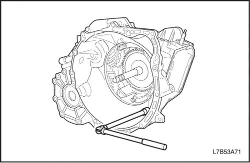
14. Remove the gearbox housing with the final drive assembly.
- Remove 17 bolts.
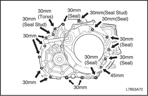
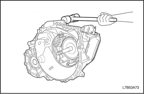
- Using a plastic hammer, remove the gearbox housing with the final drive assembly.
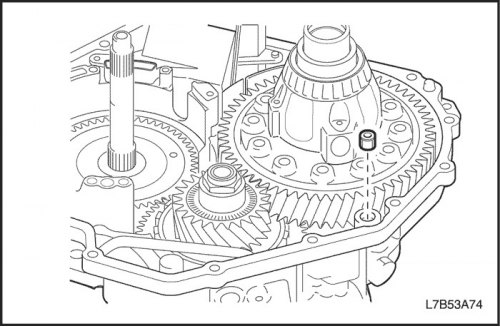
15. Remove the oil channel gasket.
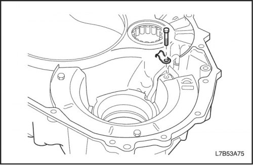
16. Remove the lubrication supply pipe to the differential gear.
- Unscrew 1 bolt and remove the clamp.
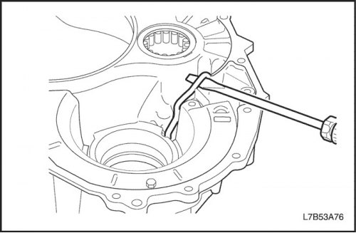
- Use a screwdriver to remove the lubrication supply tube to the differential gear.
Important: Be careful not to bend or damage the supply tube.
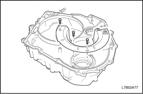
17. Remove the oil tank retaining plate (gearbox housing with final drive assembly).
- Remove 3 bolts and oil tank retaining plate.
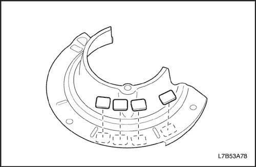
- Remove 4 magnets from the oil tank retaining plate.
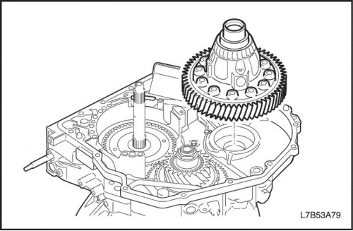
18. Remove the differential assembly.
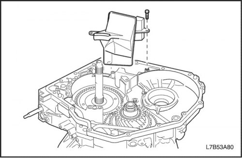
19. Remove the oil filter.
- Unscrew 1 bolt and remove the oil filter.
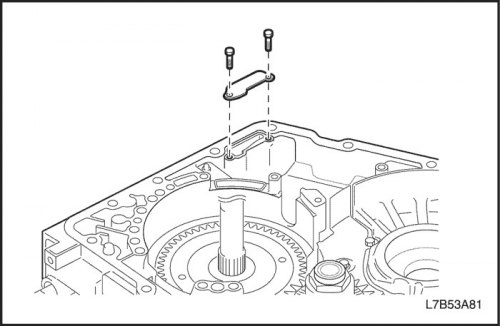
20. Remove the gearbox housing plate with the final drive assembly.
- Unscrew 2 bolts and remove the gearbox housing plate with the final drive assembly.
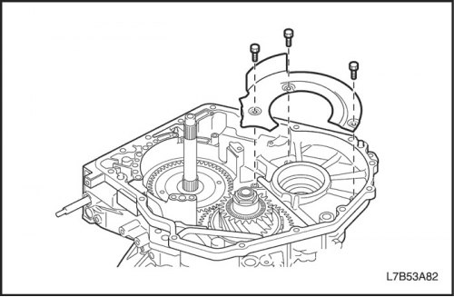
21. Remove the oil tank retaining plate (gearbox housing with final drive assembly).
- Remove 3 bolts and oil tank retaining plate.
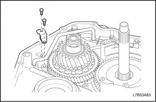
22. Remove the downshift brake supply pipe (B4).
- Unscrew 2 bolts and remove the clamp.
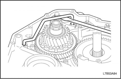
- Use a screwdriver to remove the brake feed pipe for the downshifting gear (B4).
Important: Be careful not to bend or damage the feed tube and sealing ring. Be careful not to damage the transmission housing with the final drive assembly.
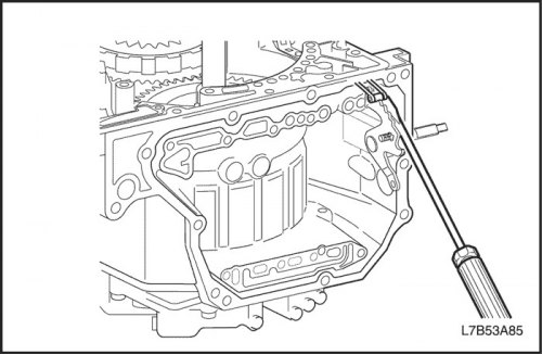
23. Remove the range selector valve lever and the parking lock mechanism rod.
- Disconnect the lock spring from the range selector valve lever.
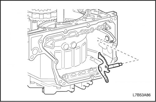
- Disconnect the range selector valve lever from the parking lock mechanism rod.
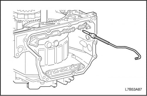
- Remove the parking lock mechanism rod.
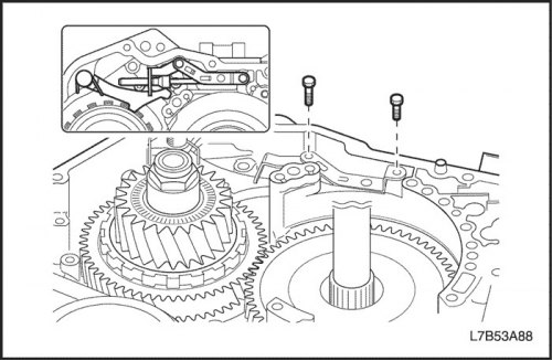
- Remove 2 bolts.
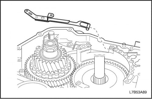
- Remove the lock spring.
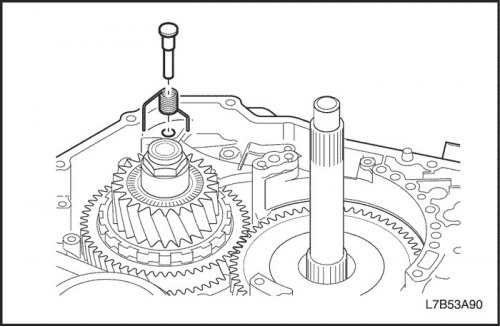
- Remove the parking lock pawl shaft and torsion spring No.1.
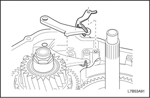
- Remove the cam plate and pawl of the parking lock mechanism.
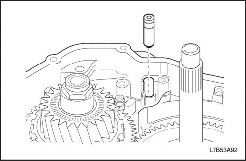
- Remove the parking lock mechanism pin.
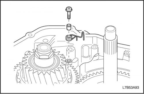
- Remove 1 Torx bolt, guide bushing and torsion spring #2.
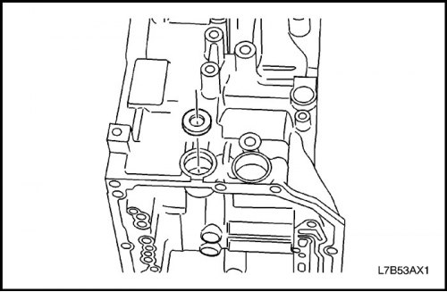
- Use a screwdriver to remove the range selection valve seal.
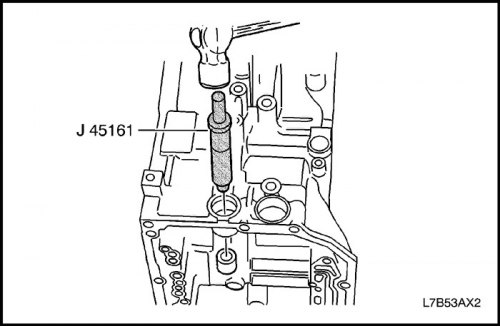
- Using J-45161 and a plastic hammer, tap the manual shift shaft bearing through the hole in the transmission housing and remove the bearing.
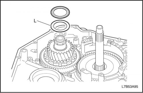
24. Remove the downshift mechanism assembly.
- Remove the thrust bearing and thrust bearing race from the underdrive assembly.
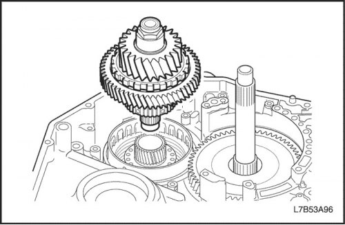
- Remove the downshift mechanism assembly from the gearbox housing with the final drive assembly.
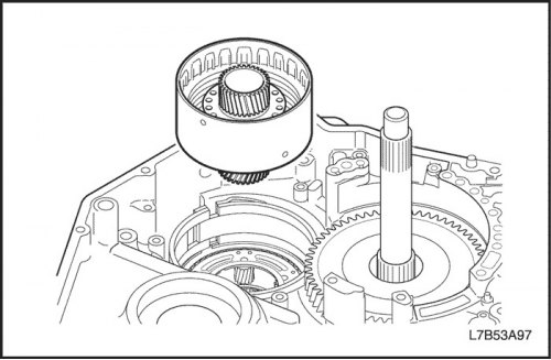
25. Remove the underdrive clutch assembly (C3).
- Remove the underdrive clutch assembly (C3).
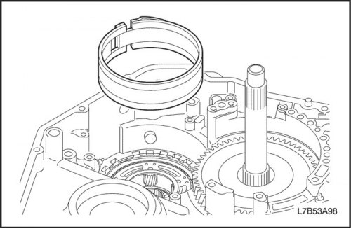
26. Remove the downshift brake band (B4).
- Remove the downshift brake band (B4).
Important: Care must be taken not to damage the gearbox housing and final drive assembly.
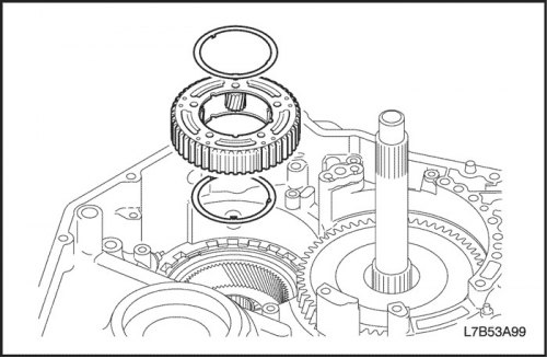
27. Remove the rear planetary gear reduction assembly.
- Remove the rear planetary gear reduction assembly.
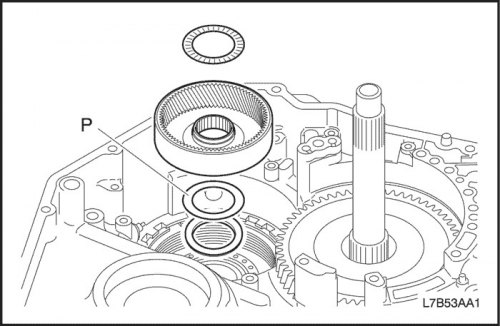
- Remove the rear planetary gear set epicyclic gear assembly for the reduction gear.
- Remove the thrust bearing and adjusting shim from the rear planetary gear set of the reduction gear.
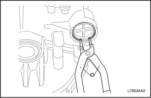
28. Remove the downshift brake piston (B4).
- Use pliers to remove the retaining ring.
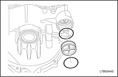
- Remove the underdrive brake cover (B4) assembly from the transaxle housing.
- Remove 2 O-rings from the underdrive brake cover (B4).
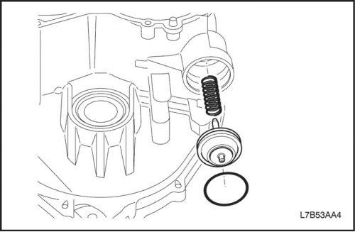
- Remove the downshift brake piston (B4) assembly and spring from the transaxle housing.
- Remove the O-ring from the underdrive brake piston (B4) assembly.
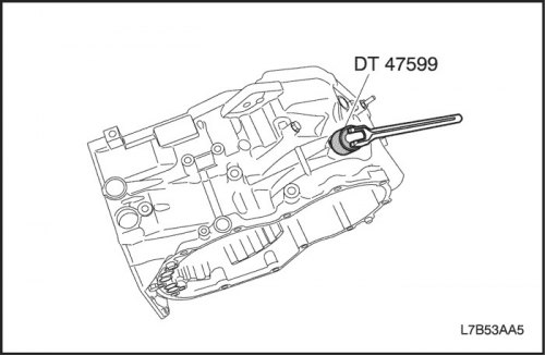
- Use the DT-47599 anchor bolt wrench to loosen the anchor bolt.
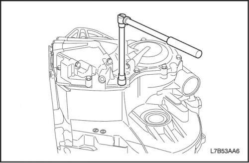
29. Remove the rear crankcase assembly.
- Remove 13 bolts.

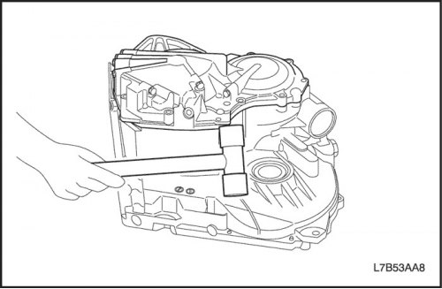
- Using a plastic hammer, remove the rear crankcase assembly.
Important: Care must be taken not to damage the rear crankcase.
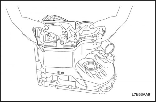
- Remove the rear crankcase assembly.
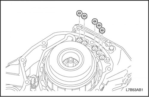
- Remove 5 gaskets from the gearbox housing with the final drive assembly.
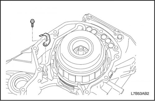
30. Remove the supply pipe.
- Remove 1 Torx bolt and remove clamp.
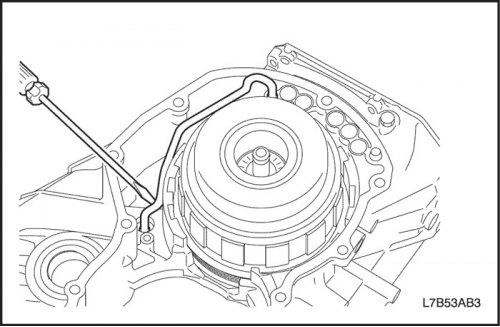
- Use a screwdriver to remove the supply pipe.
Important: Be careful not to bend or damage the supply tube.
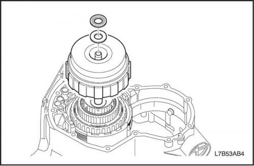
31. Remove the forward clutch (C1) and direct drive (C2).
- Remove the forward clutch (C1) and direct drive clutch (C2) as an assembly.
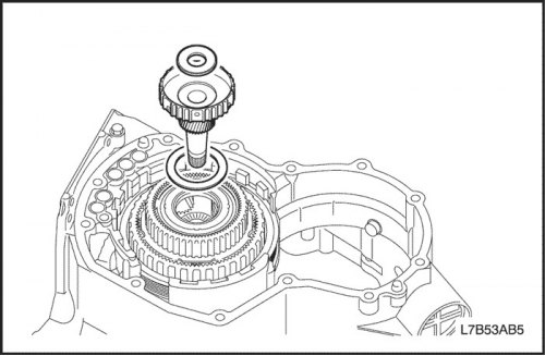
32. Remove the planetary gear sun wheel assembly.
- Remove the planetary gear sun wheel assembly.
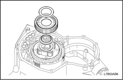
33. Remove the front planetary gear epicyclic wheel assembly.
- Remove the front planetary gear epicyclic wheel assembly.
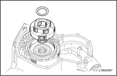
34. Remove the planetary gear assembly.
- Remove the planetary gear assembly.
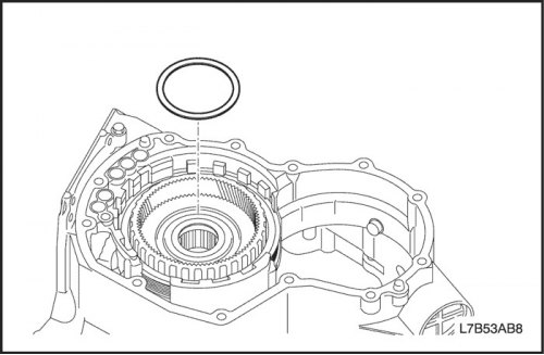
35. Remove the front epicyclic gear with overrunning clutch No.2 (F2) and the plate, disc and flange of the 1st gear and reverse brake (B3).
- Remove the bearing with the race.
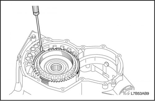
- Remove the retaining ring with a screwdriver.
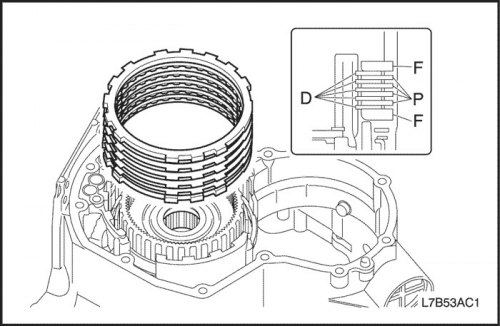
- Remove the plate, disc and flange.

- Remove the front epicyclic gear and overrunning clutch No.2 (F2).
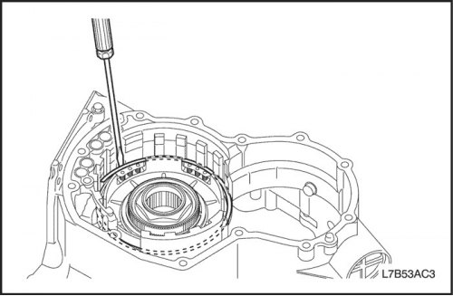
- Use a screwdriver to remove the retaining ring.
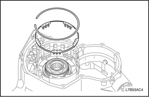
- Remove the return spring assembly from the 1st gear and reverse brake (B3).
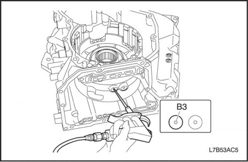
Caution: When working with compressed air, wear protective glasses to prevent eye injury.
36. Remove the 1st gear and reverse brake piston (B3).
- While pressing the piston by hand, supply compressed air (4 kg/cm?) to the lubrication channel of the gearbox housing with the main gear assembly, as shown in the figure, and remove piston B3.
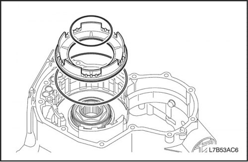
- Remove the sealing rings from the piston.
37. Check the condition of the 1st gear and reverse brake disc and plate (B3).
- Make sure there is no wear or burnout on the sliding surface of the discs. Replace parts if necessary.
Important: Before replacing, soak new discs in the automatic transmission fluid for at least 2 hours.
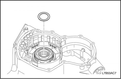
38. Remove the thrust bearing race.
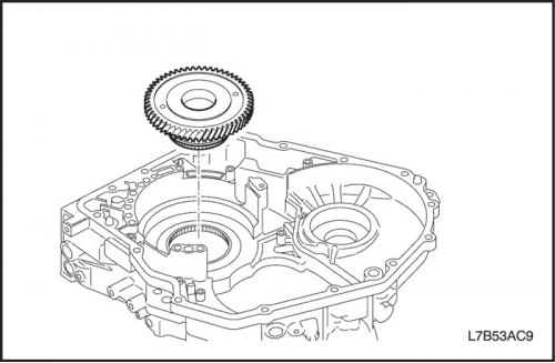
- Remove the collar from the intermediate shaft drive gear.
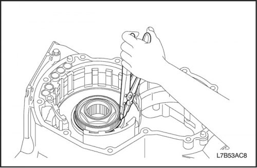
39. Remove the intermediate shaft drive gear.
- Use pliers to remove the retaining ring.
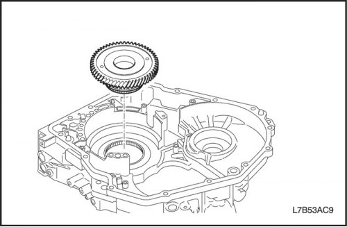
- Remove the intermediate shaft drive gear.
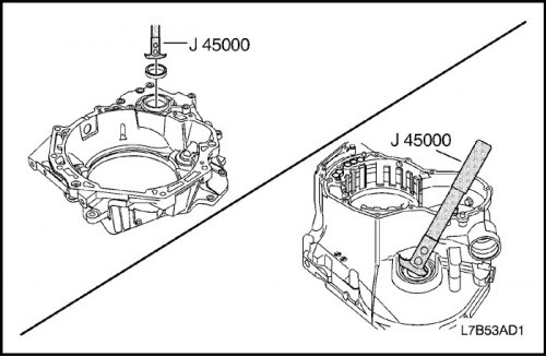
40. Remove the oil seal.
- Remove the oil seal from the crankcase side and the gearbox housing side using the J-45000 seal puller.
The original material is located on the website «ChevyMan»