
Necessary equipment
- J-45053 Universal Clamp Press
- DT-47599 Anchor Bolt Wrench
- DT-47687 Torque Converter
- J-45187 Differential Secondary Shaft Seal Installer
- J-44809 Secondary Shaft Seal Installer
- J-45124 Dismantling Bridge
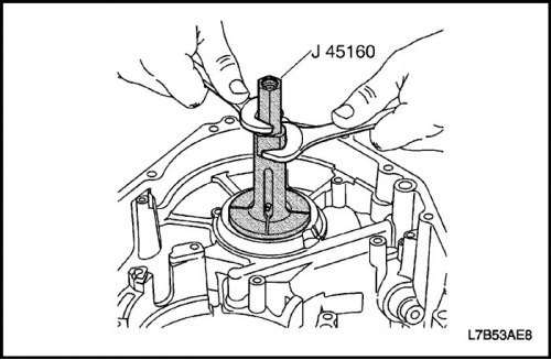
- J-45160 Differential Bearing Race Puller
- J-8092 Guide Handle
- J-45184 Differential Bearing Race Installer
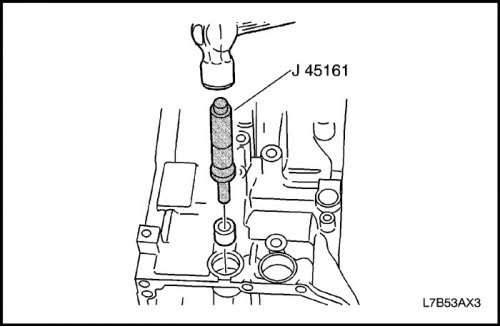
- J-45161 Manual Shift Shaft Bearing Replacement Puller
- J-45404 Gearbox Alignment Tool with Indicator
Assembly order
1. Install the intermediate shaft drive gear.
- Install the intermediate shaft drive gear.
- Use pliers to install the retaining ring.
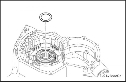
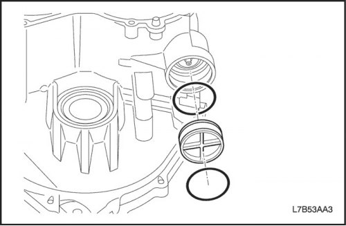
2. Install the 1st gear and reverse brake piston (B3).
- Lubricate the new sealing rings with automatic transmission fluid and install them on the piston.
- Lubricate the inner surface of the gearbox housing with the final drive assembly with automatic transmission working fluid.
- Press the 1st and reverse brake piston (B3) into the gearbox housing with the final drive assembly.
Important: Be careful not to damage the sealing ring.
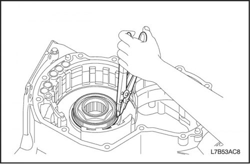
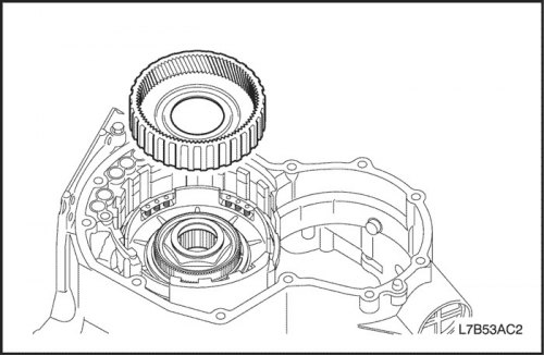
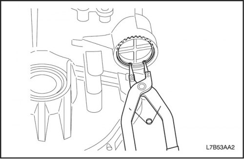
3. Install the 1st and reverse brake return spring assembly (B3).
- Install the 1st and reverse brake return spring assembly (B3) onto the B3 piston.
- While compressing the 1st gear and reverse brake return spring (B3) by hand, use a screwdriver to install the retaining ring into the groove.

Important: Be careful not to damage the inside surface of the gearbox housing with the final drive assembly. Make sure that the snap ring is installed correctly as shown in the figure.
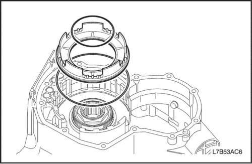
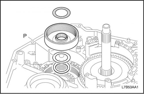
4. Install the front epicyclic gear with overrunning clutch No.2 (F2) and the flange, disc and plate of the 1st gear and reverse brake (B3).
- Install the collar on the intermediate shaft drive gear.
- Install the front epicyclic gear and overrunning clutch No.2 (F2).
Important: Make sure the epicyclic gear turns freely counterclockwise and locks when turned clockwise.
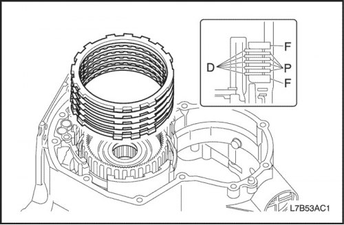
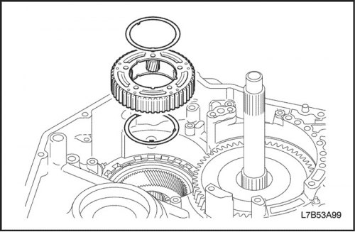
- Install the flange, disc and plate as shown in the figure.
Important: Make sure that their number and order are correct.
- Order: F - D - P - D - R - D - P - D - P - D - F
|
Clutch and brake
|
Flange (F)
|
Plate (P)
|
Disk (D)
|
|
|
1st gear and reverse brake (B3)
|
2
|
4
|
5
|
|
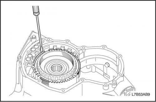
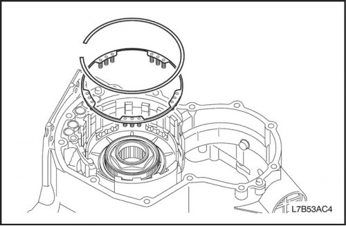
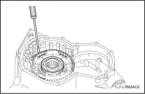
- Using a screwdriver, install the retaining ring.
Important: Make sure that the cut of the retaining ring does not coincide with one of the notches.
Caution: When working with compressed air, wear protective glasses to prevent eye injury.
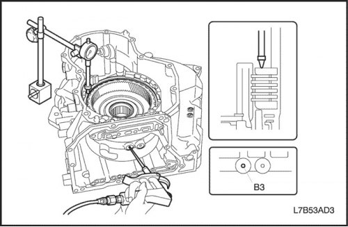
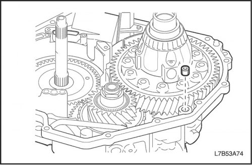
5. Check the piston stroke of the 1st gear and reverse brake (B3).
- Install the indicator as shown in the figure.
- Apply compressed air (4 kg/cm?) and measure the piston stroke of the 1st gear and reverse brake (B3).
- Piston stroke: 1.39-2.21 mm (0.055 - 0.087 inches).
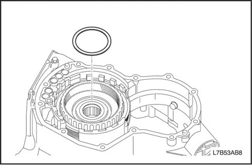
6. Install the planetary gear assembly.
- Install the planetary gear assembly.
Important: Make sure that the thrust bearing is in the correct direction.
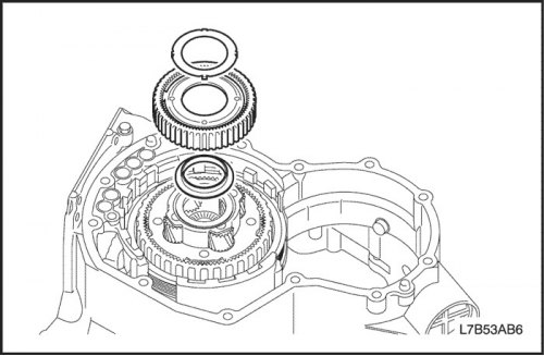
7. Install the front planetary gear epicyclic wheel.
- Install the front planetary gear epicyclic wheel.
Important: Make sure that the thrust bearing is in the correct direction.
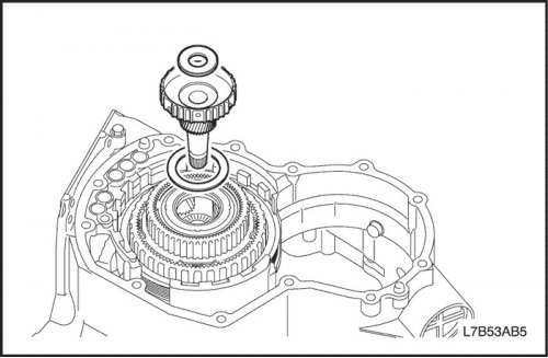
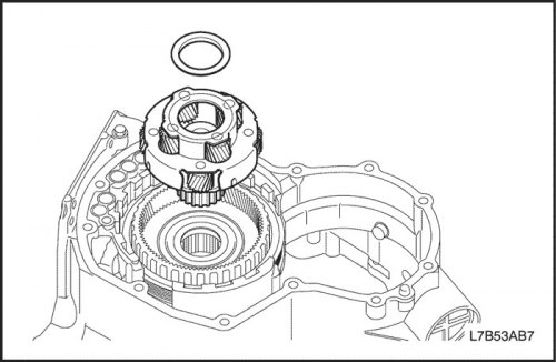
8. Install the planetary gear sun wheel assembly.
- Install the planetary gear sun wheel assembly.
Important: Make sure that the thrust bearing is in the correct direction.
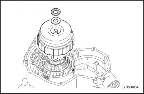
9. Install the forward clutch (C1) and direct drive (C2).
- Install the forward clutch (C1) and direct drive clutch (C2) as an assembly.
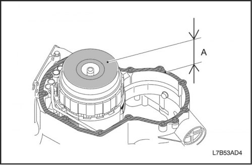
- Check distance "A".
- A: 50.850 - 51.825 mm (2.002-2.040 inches)
Important: If the distance is not within the standard, adjust again until the standard is reached.
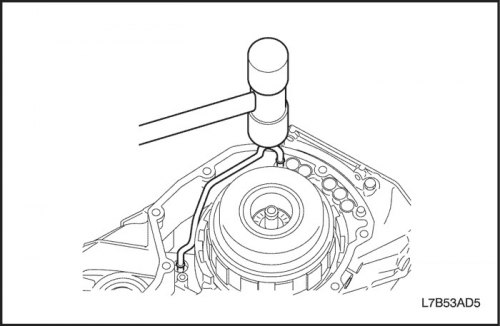
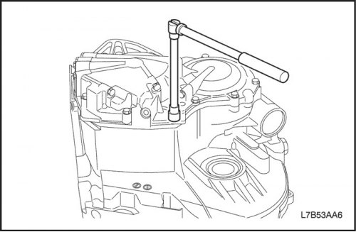
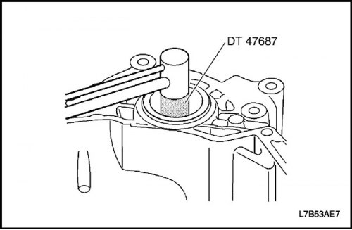
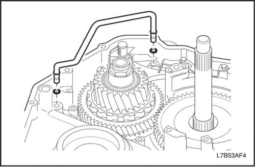
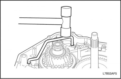
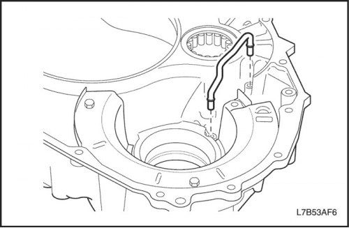
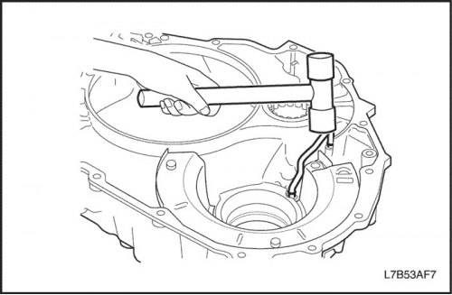
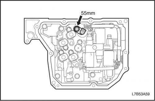
10. Install the supply pipe.
- Using a plastic hammer, install the supply pipe as shown in the figure.
Important: Be careful not to bend or damage the supply tube.
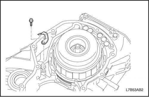
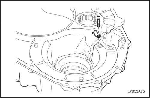
- Install 1 clamp and tighten 1 Torx bolt.
Tighten
Tighten the oil supply pipe clamp mounting bolt to 6 N·m (53 lbs.in).
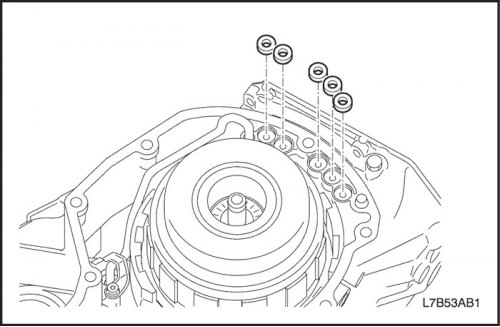
11. Install the rear crankcase assembly.
- Apply grease to 5 new gaskets and install them into the gearbox housing with the final drive assembly.
- Install 3 new O-rings and bearing race into the rear crankcase.
- Clean the mating surfaces of the rear housing and the gearbox housing with the final drive assembly from traces of packaging material and wipe off the automatic transmission fluid from the mating surfaces.
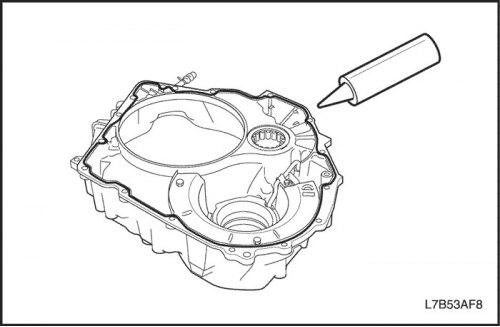
- Apply plastic gasket (FIPG) to the rear crankcase as shown in the figure.
Important: Ensure that there is no oil on the mating surfaces of the rear case and the gearbox housing with the final drive assembly.
- Install the rear crankcase.
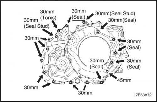
- Install and tighten the 13 bolts.
Tighten
Tighten the rear crankcase mounting bolt to 30 Nm (22 ft·lbs).

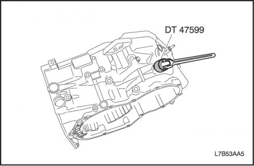
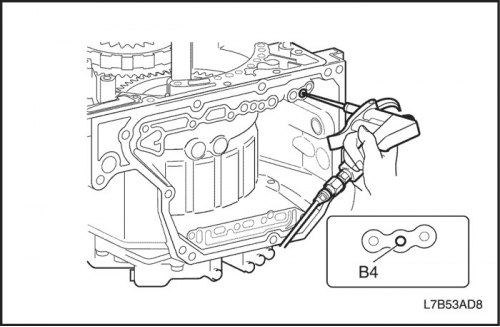
12. Install the downshift brake (B4).
- Lubricate the new O-ring with automatic transmission fluid, install and tighten 1 anchor bolt using the DT-47599 anchor bolt wrench.
Tighten
Tighten the underdrive brake anchor bolt (B4) to 167 Nm (123 ft·lbs).
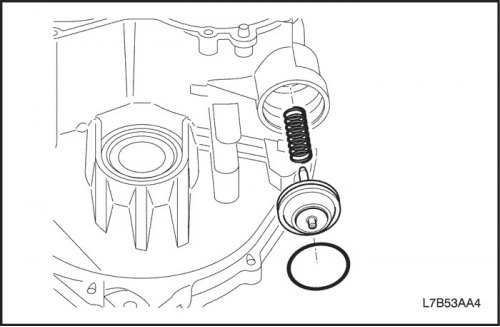
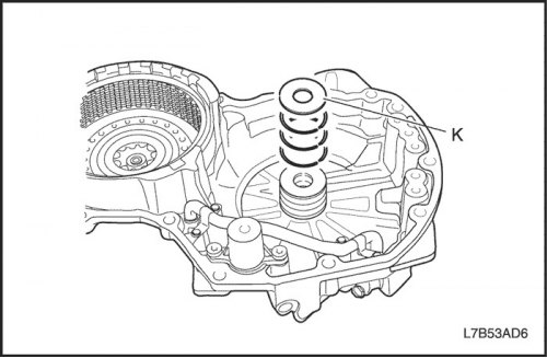
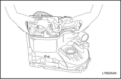
13. Install the downshift brake piston (B4).
- Lubricate the inner surface of the gearbox housing with the final drive assembly with automatic transmission working fluid.
- Install the downshift brake spring and piston (B4) assembly into the transaxle housing.
- Lubricate 2 new O-rings with automatic transmission fluid and install them into the downshift brake cover (B4).
- While pressing on the downshift brake cover (B4), use pliers to install the retaining ring.
Important: If the retaining ring is deformed, replace it.
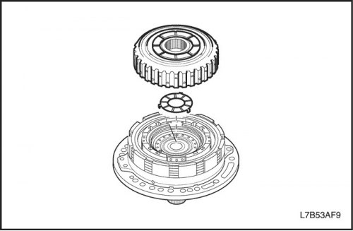
14. Install the rear planetary gear reduction assembly.
- Install the rear planetary gear set epicyclic gear assembly for the reduction gear.
|
Component name
|
Technical specifications
|
Designation
|
|
Washer thickness type
|
0.81 mm (0.032 inches)
|
8
|
|
0.90 mm (0.035 inches)
|
9
|
|
|
1.00 mm (0.039 inches)
|
10
|
|
|
1.10 mm (0.043 inches)
|
11
|
|
|
1.20 mm (0.047 inches)
|
12
|
|
|
1.30 mm (0.051 inches)
|
13
|
|
|
1.40 mm (0.055 inches)
|
14
|
|
|
1.50 mm (0.059 inches)
|
15
|
|
|
1.60 mm (0.063 inches)
|
16
|
- Install the rear planetary gear reduction assembly.
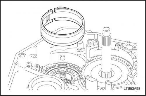
15. Install the downshift brake band (B4).
- Install the downshift brake band (B4).
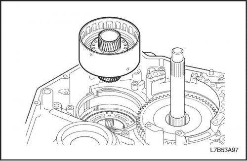
16. Install the underdrive clutch (C3) assembly.
- Install the underdrive clutch (C3) assembly.
Caution: When working with compressed air, wear protective glasses to prevent eye injury.
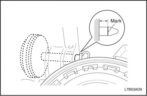
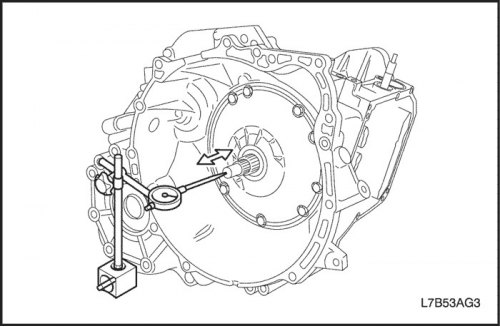
17. Check the stroke of the downshift brake piston (B4).
- Place a mark on the downshift brake piston rod (B4).
- Measure the stroke of piston B4 by supplying and releasing compressed air (4 kg/cm?) as shown in the figure.
- Piston stroke: 5.76-6.76 mm (0.227-0.266 inches)
If the stroke of the rod is not within the norm, select another rod.
|
Rod length
|
R=76.2 mm (3,000 inches)
|
|
R=76.7 mm (3.020 inches)
|
|
|
R=77.2 mm (3.039 inches)
|
|
|
R=77.7 mm (3.059 inches)
|
|
|
R=78.2 mm (3.079 inches)
|
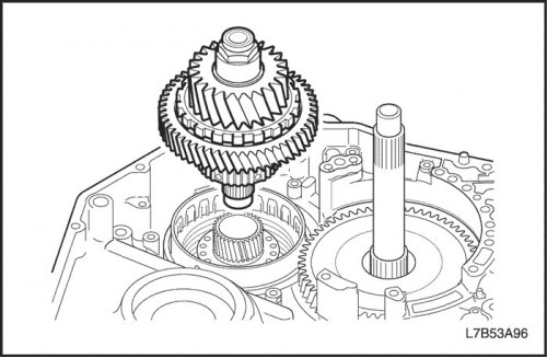
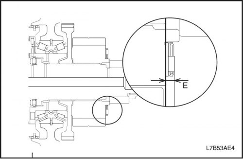
18. Install the reduction gear assembly.
- Install the reduction gear assembly into the gearbox housing with the final drive assembly.
- Install the thrust bearing and race.
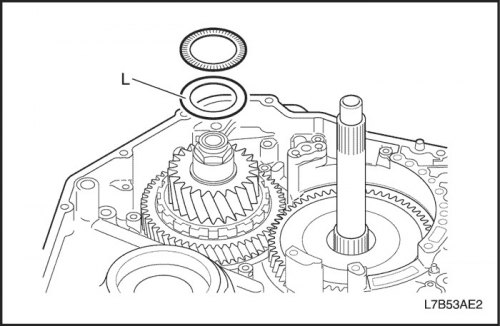
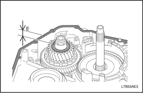
- Check distance E.
Important: Measure from the end surface of the crankcase to the bearing (part of the video).
- E: 1.269-1.645 mm (0.050-0.065 inches)
If the measured value is not within the norm, select the "L" clip for installation.
|
Component name
|
Technical specifications
|
Designation
|
|
Washer thickness type
|
0.80 mm (0.031 inches)
|
(No)
|
|
0.90 mm (0.035 inches)
|
A
|
|
|
1.00 mm (0.039 inches)
|
B
|
|
|
1.10 mm (0.043 inches)
|
C
|
|
|
1.20 mm (0.047 inches)
|
D
|
|
|
1.30 mm (0.051 inches)
|
E
|
|
|
1.40 mm (0.055 inches)
|
F
|
|
|
1.50 mm (0.059 inches)
|
G
|
And if the value is not completely within the norm when using the above-mentioned sleeves, select the adjusting shim "P" according to the item "14. Install the rear planetary reduction gear assembly" for installation.
In this case, with the "L" clip, the thickness = 0.80 mm should be used (0.031 inches).
19. Adjust the preload of the tapered roller bearing.
- Install the differential housing assembly into the gearbox housing with the final drive assembly.
- Install the gearbox housing with the final drive assembly into the gearbox housing with the final drive assembly.
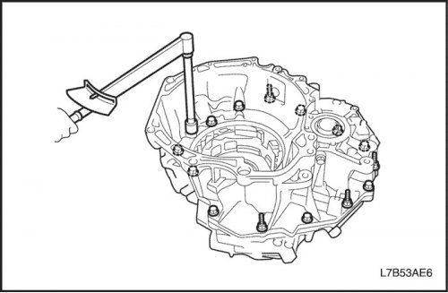
- Install and tighten the 17 bolts as shown.
Tighten
Tighten the gearbox housing mounting bolt with the final drive assembly to a torque of 30 N·m (22 ft·lbs).

- Rotate the differential in both directions to seat the bearing tightly.
- Using the DT-47687 torque transducer and torque gauge, measure the preload (when rotating) side bearing without installing the reduction gear mechanism and shaft assembly.
- Torque characteristic (new bearing): 0.70-1.20 Nm (6-11 lbs.in).
- If the preload does not meet the specification, the differential bearing race adjusting shim must be replaced.
- Remove the gearbox housing with the final drive assembly and the differential assembly from the gearbox housing with the final drive assembly.
20. Remove the differential bearing race and adjusting shim.
- Install J-45160 into the bearing race, ensuring that the bottom of the tool is fully seated down inside the race and sits flush on the top of the adjusting shim before tightening.
- Using two wrenches, tighten J-45160 until the tool is firmly seated in the bearing race for removal.
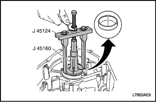
- Position the J-45124 adjustable axle mount sections so they are perpendicular to the top of the housing section around the differential bearing race.
- Attach J-45124 to J-45160 and lightly press down, hand tightening the center bolt to prevent the tool assembly from moving. Recheck the position of the J-45124 axle adjuster mounts to ensure that the differential bearing race will not bind on the adjuster mounts and that the transaxle case will not be damaged when the bearing race is removed.
- Tighten bolt on J-45124 to remove differential bearing race from transaxle housing.

- Remove the differential bearing race adjusting shim from the gearbox housing with the final drive assembly.
- Measure the adjustment gasket of the differential bearing cage to determine its size. Based on the resulting measurement value, see the following table to determine the correct size of the adjustment pad that will be required.
|
1.00 mm (0.039 inches)
|
1.48 mm (0.058 inches)
|
|
1.05 mm (0.041 inches)
|
1.51 mm (0.059 inches)
|
|
1.10 mm (0.043 inches)
|
1.54 mm (0.061 inches)
|
|
1.15 mm (0.045 inches)
|
1.57 mm (0.062 inches)
|
|
1.20 mm (0.047 inches)
|
1.60 mm (0.063 inches)
|
|
1.25 mm (0.049 inches)
|
1.65 mm (0.065 inches)
|
|
1.30 mm (0.051 inches)
|
1.70 mm (0.067 inches)
|
|
1.33 mm (0.052 inches)
|
1.75 mm (0.069 inches)
|
|
1.36 mm (0.053 inches)
|
1.80 mm (0.071 inches)
|
|
1.39 mm (0.055 inches)
|
1.85 mm (0.073 inches)
|
|
1.42 mm (0.056 inches)
|
1.90 mm (0.075 inches)
|
|
1.45 mm (0.057 inches)
|
-
|
If the measured torque value is lower than the specifications listed, a larger/thicker shim is required. If the measured torque value is higher than the specifications listed, a smaller/thinner shim is required.
21. Remove the differential bearing race and adjusting shim.
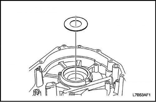
- After selecting the correct shim, install the new differential bearing race shim into the transaxle housing.
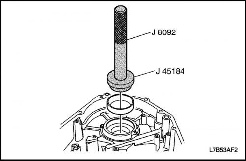
- Using J-8092 and J-45184, install the differential bearing race into the transaxle housing.
- After the differential bearing race has been correctly installed into the housing, repeat the measurement to ensure that the correct shim thickness has been selected.
22. Install the manual shift shaft bearing.
- Using J-45161 and a plastic hammer, install the manual shift shaft bearing into the transaxle housing.
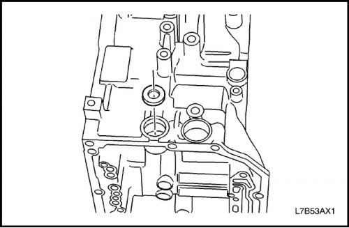
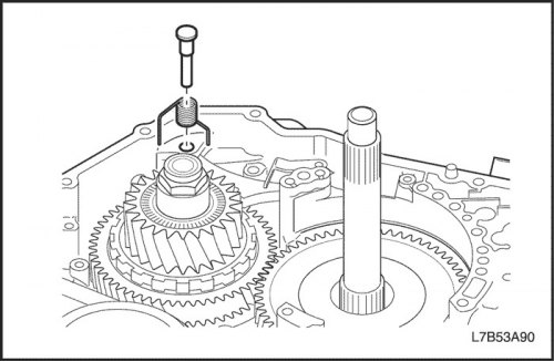
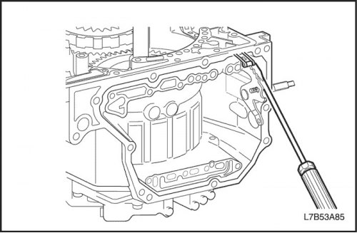
23. Install the range selector valve seal by pressing the seal into the housing.
- Install the new range selector valve seal by pressing the seal into the housing.
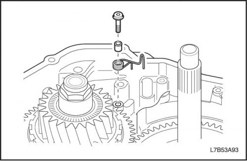
- Install 1 Torx bolt, guide bushing and torsion spring #2.
Tighten
Tighten torsion spring mounting bolt No.2 to 10 N·m (89 lbs.in).
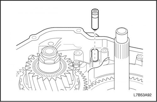
- Install the parking lock mechanism pin.
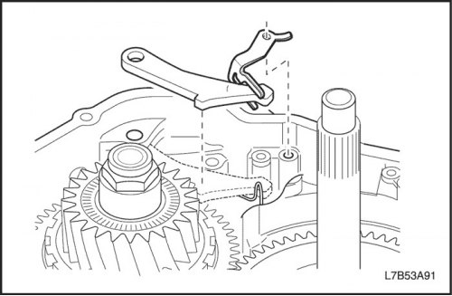
- Install the cam plate and pawl of the parking lock mechanism.
- Install the parking lock pawl shaft and torsion spring No.1.
- Install the lock spring.
- Temporarily tighten 2 bolts.
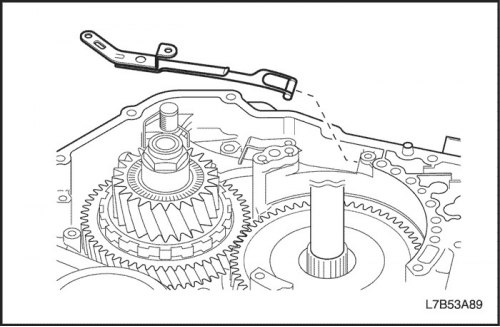
- Install the parking lock mechanism rod.
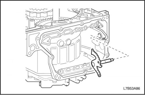
- Install the range selector valve lever and attach the parking lock mechanism rod to it.
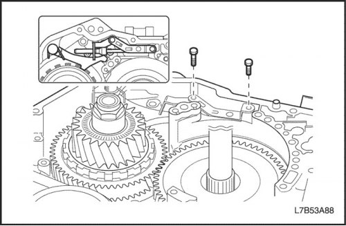
- Use a screwdriver to connect the locking spring to the range selector valve lever.

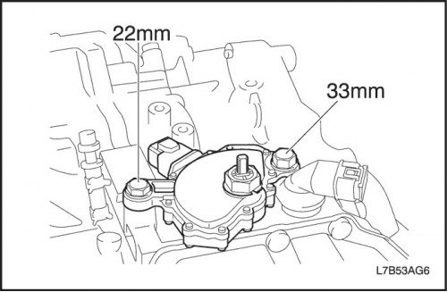
- Secure with two bolts.
Tighten
Tighten the bolt (1) securing the locking spring (16.7 mm) to a torque of 10 N·m (89 lbs.in).
Tighten the bolt (2) securing the locking spring (14 mm) to 6 Nm (53 lbs.in).
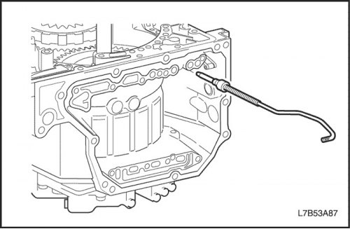
24. Install the downshift brake supply pipe (B4).
- Install 2 new O-rings into the groove of the tube and use a plastic hammer to install the feed tube to the downshift brake (B4).
Important: Be careful not to damage the O-ring or bend or damage the tube.
- Install the clamp and tighten the 2 bolts.
Tighten
Tighten the downshift brake line clamp bolt (B4) to 6 Nm (53 lbs.in).
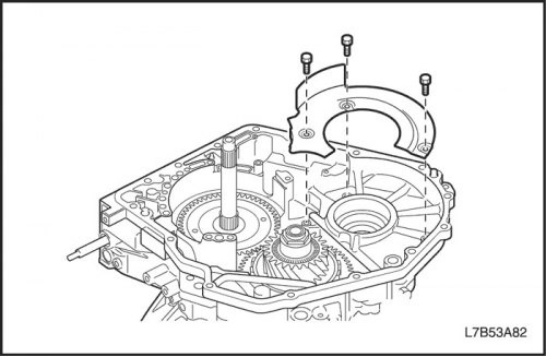
25. Install the oil tank retaining plate (gearbox housing with final drive assembly).
- Install the oil tank retaining plate and tighten the 3 bolts.
Tighten
Tighten the oil tank retaining plate mounting bolt (gearbox housing with final drive assembly) torque 6 Nm (53 lbs.in).
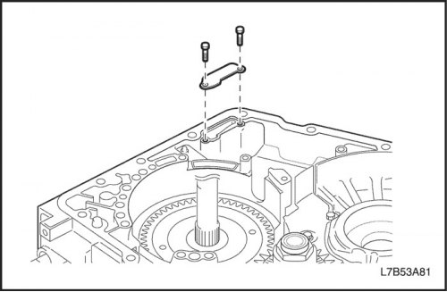
26. Install the gearbox housing plate with the final drive assembly.
- Install the gearbox housing plate with the final drive assembly and tighten the 2 bolts.
Tighten
Tighten the gearbox housing plate mounting bolt with the final drive assembly to 6 N·m (53 lbs.in).
27. Install the oil filter.
- Install the oil filter and tighten 1 bolt.
Tighten
Tighten the oil filter mounting bolt to 6 Nm (53 lbs.in).
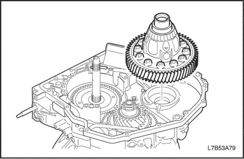
28. Install the differential assembly.
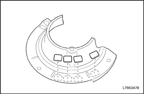
29. Install the oil tank retaining plate (gearbox housing with final drive assembly).
- Install 4 magnets on the oil tank retaining plate.
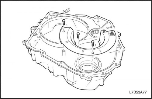
- Install the oil tank retaining plate and tighten the 3 bolts.
Tighten
Tighten the oil tank retaining plate mounting bolt (gearbox housing with final drive assembly) torque 6 Nm (53 lbs.in).
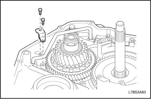
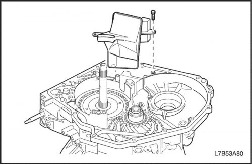
30. Install the lubrication supply pipe to the differential gear.
- Using a plastic hammer, install the grease supply tube to the differential gear.
Important: Be careful not to bend or damage the tube.
- Install the clamp and tighten 1 bolt.
Tighten
Tighten the differential gear oil supply tube clamp mounting bolt to 6 Nm (53 lbs.in).
31. Install the gasket.
- Install 1 new gasket.
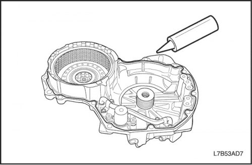
32. Assemble the gearbox housing with the final drive assembly.
- Clean the parts from traces of packaging material. Do not allow oil to come into contact with the mating surfaces of the gearbox housing with the final drive assembly and the gearbox housing with the final drive assembly.
- Apply plastic gasket (FIPG) to the gearbox housing with final drive assembly as shown in the figure.
- Install the gearbox housing with the final drive assembly into the gearbox housing with the final drive assembly.
- Install and tighten the 17 bolts as shown.
Tighten
Tighten the gearbox housing mounting bolt with the final drive assembly to a torque of 30 N·m (22 ft·lbs).
Important: Be sure to use a new sealing bolt.
33. Install the oil pump assembly.
- Install the thrust ring with grease into the oil pump assembly.
- Install the 2nd gear overrun brake hub (B1) and 2nd gear brake hub (B2) and overrunning clutch No.1 (F1) to the oil pump assembly.
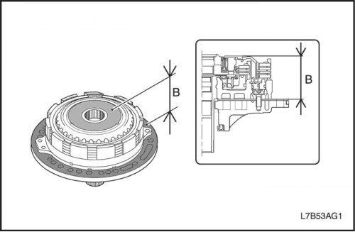
- Check distance B.
- B: 51.09-51.71 mm (2.011-2.036 inches)
Important: If the distance is not within the standard, adjust again until the standard is reached.
- Install a new O-ring into the oil pump assembly.
- Install the oil pump assembly on the primary shaft in a horizontal position and align the bolt holes in the pump housing with the holes in the gearbox housing with the final drive assembly. Lightly press the oil pump housing.
Important: Be careful not to drop the 2nd gear overrun brake hub (B1) and 2nd gear brake hub (B2) and the overrunning clutch No.1 (F1).
- Install and tighten 8 bolts.
Tighten
Tighten the oil pump assembly mounting bolt to 25 N·m (18 ft·lbs).
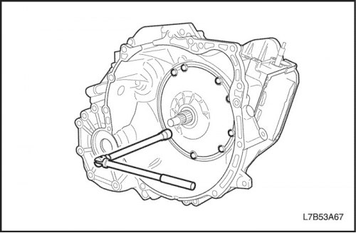
34. Check the axial clearance.
- Install the indicator as shown in the figure, move the input shaft and measure the axial clearance.
- Axial clearance: 0.188 - 0.570 mm (0.007 - 0.022 inches).
If the axial clearance is not within the standard, select another bearing race "K" according to item "No. 11, 2) Assembly of the main unit" in this section.
|
Component name
|
Thickness characteristics
|
O.D
|
Inner diameter
|
Designation
|
|
Washer thickness type
|
0.81 mm (0.032 inches)
|
41.00 mm (1.614 inches)
|
22.00 mm (0.866 inches)
|
(No)
|
|
0.90 mm (0.035 inches)
|
41.00 mm (1.614 inches)
|
22.00 mm (0.866 inches)
|
9
|
|
|
1.00 mm (0.039 inches)
|
41.00 mm (1.614 inches)
|
21.70 mm (0.854 inches)
|
10
|
|
|
1.10 mm (0.043 inches)
|
41.00 mm (1.614 inches)
|
21.50 mm (0.846 inches)
|
11
|
|
|
1.20 mm (0.047 inches)
|
41.00 mm (1.614 inches)
|
21.30 mm (0.839 inches)
|
12
|
|
|
1.30 mm (0.051 inches)
|
41.00 mm (1.614 inches)
|
21.20 mm (0.835 inches)
|
13
|
|
|
1.40 mm (0.055 inches)
|
41.00 mm (1.614 inches)
|
21.00 mm (0.827 inches)
|
14
|
|
|
1.50 mm (0.059 inches)
|
41.00 mm (1.614 inches)
|
20.80 mm (0.819 inches)
|
15
|
35. Install the switch and sensor assembly into the gearbox housing with the final drive assembly.
- Install a new sealing ring using automatic transmission fluid onto the transmission harness with the final drive assembly.
- Install the switch and sensor assembly into the gearbox housing with the final drive assembly.
36. Install the gasket.
- Install 2 new gaskets into the gearbox housing with the final drive assembly.
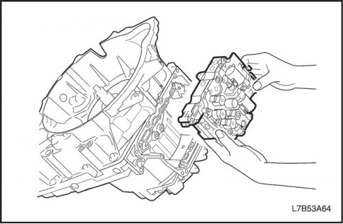
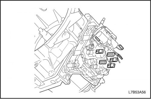
37. Install the valve body.
- While holding the valve block assembly, connect the range select valve connecting rod to the range select valve lever.
Important: The gear shift position is "N".
Important: Be careful not to damage the transmission harness.
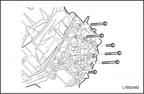
- Install and tighten 6 bolts evenly.
Tighten
Tighten the valve block assembly mounting bolt to 10 Nm (89 lbs.in).
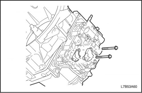
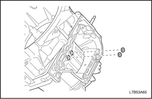
38. Install the cover on the suction side.
- Install new gasket and cover on suction side, tighten 2 bolts evenly.
Tighten
Tighten the cover mounting bolt on the suction side to 10 Nm (89 lbs.in).
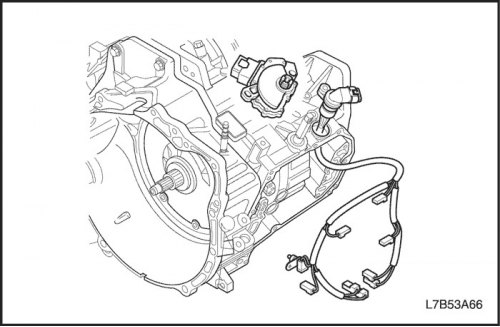
39. Connect the transmission wire connectors to the final drive assembly.
- Lubricate the new sealing ring with automatic transmission fluid and install it in the groove of the automatic transmission fluid temperature sensor.
- Install the clamp and tighten 1 bolt.
Tighten
Tighten the transmission fluid temperature sensor mounting bolt to 10 Nm (89 lbs.in).
- Connect 8 wire connectors of solenoid valves.
Important: Be careful not to bend the solenoid valve connector pin.
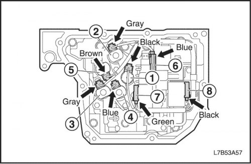
(1) Solenoid valve No.1 (black)
(2) Solenoid valve No.2 (gray)
(3) Solenoid valve No.3 (gray)
(4) Solenoid valve No.4 (blue)
(5) Solenoid valve No.5 (brown)
(6) Solenoid valve (blue)
(7) Solenoid valve (green)
(8) Solenoid valve (black)
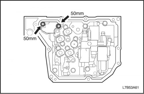
40. Install the rear cover of the gearbox housing with the final drive assembly.
- Clean the mating surface of the gearbox housing with the final drive assembly from traces of packaging material and wipe off oil from the mating surface.
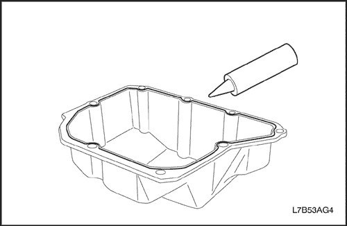
- Apply plastic gasket (FIPG) to the new rear transmission housing cover.
Important: Make sure that there is no oil on the mating surface.
- Install the rear cover of the gearbox housing with the final drive assembly onto the gearbox housing with the final drive assembly.
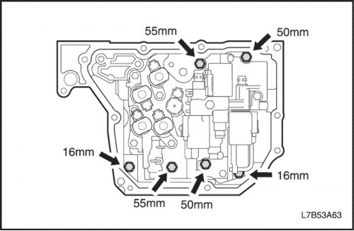
- Install and tighten 9 new Torx bolts evenly.
Tighten
Tighten the rear gearbox housing cover mounting bolts to 13 Nm (10 ft·lbs).
Important: Be sure to use a new sealing bolt.
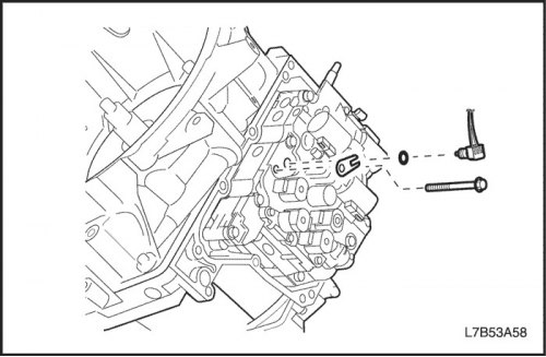
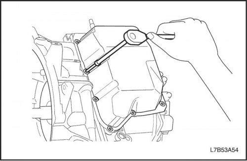
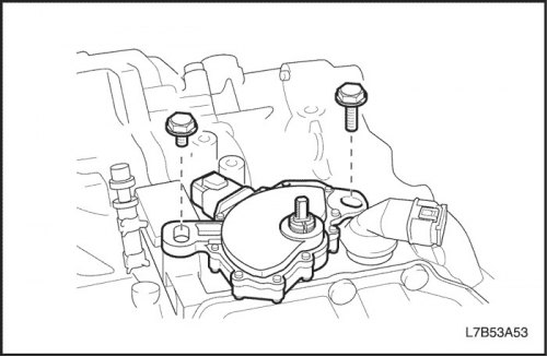
41. Install the input shaft speed sensor and the automatic transmission range switch.
- Install a new sealing ring, lubricated with automatic transmission fluid, onto the input shaft speed sensor.
- Install the input shaft speed sensor and tighten 1 bolt.
Tighten
Tighten the input shaft speed sensor mounting bolt to 6 Nm (53 lbs.in).
Important: Be sure to use a new sealing bolt.
- Install the automatic transmission range switch onto the range selection valve lever.
- Temporarily tighten 2 bolts.
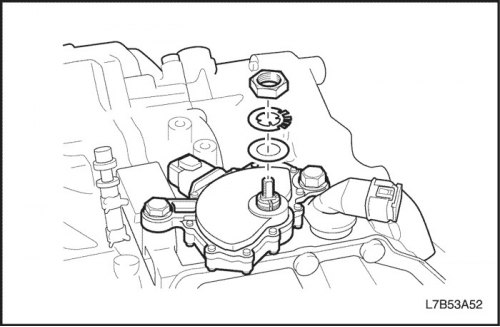
- Install the spring washer with nut and tighten the nut.
Tighten
Tighten the automatic transmission range selector nut to 7 Nm (62 lbs.in).
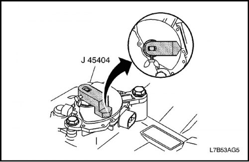
- The range selector valve lever must be adjusted to the "N" position.
- Install J-45404 to the range select valve lever.
- Rotate the transmission range selector until the neutral reference line on the selector is aligned with the pointer line on J-45404.
- Tighten the 2 automatic transmission range selector bolts.
Tighten
Tighten the automatic transmission range selector bolts to 25 Nm (18 ft·lbs).
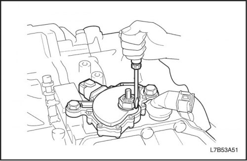
- Use a screwdriver to tighten the spring washer.
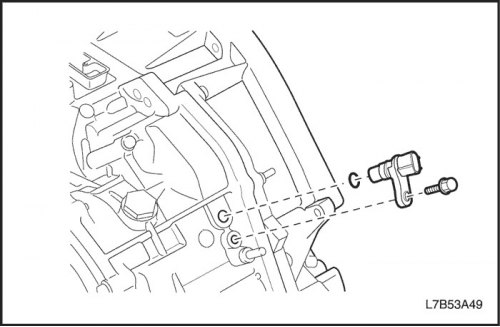
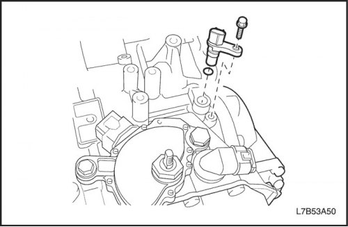
42. Install the secondary shaft speed sensor.
- Install a new sealing ring, lubricated with automatic transmission fluid, onto the secondary shaft speed sensor.
- Install the secondary shaft speed sensor and tighten 1 bolt.
Tighten
Tighten the secondary shaft speed sensor mounting bolt to 6 Nm (53 lbs.in).
Important: Be sure to use a new sealing bolt.
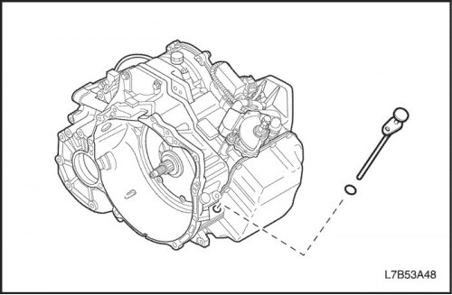
43. Install the oil level sensor.
- Install a new sealing ring, lubricated with automatic transmission fluid, and an oil level sensor.
- Tighten 1 bolt.
Tighten
Tighten the oil level sensor mounting bolt to 10 Nm (89 lbs.in).
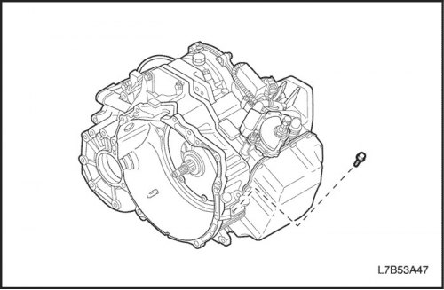
44. Replace the drain plug.
- Install a new gasket on the drain plug.
Tighten
Tighten the drain plug to 40 Nm (30 lbs per foot).
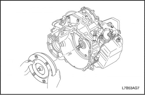
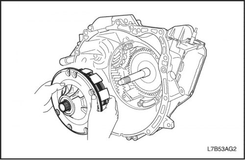
45. Install the torque converter.
- Install the torque converter.
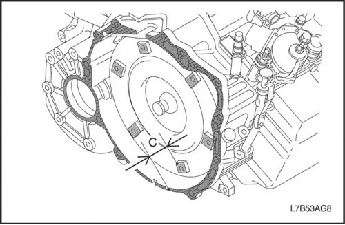
- Check distance C.
- C = 1.35 mm (0.053 inches)
Important: If the distance is not within the standard, adjust again until the standard is reached.
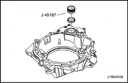
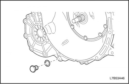
46. Install the differential seal.
- Install the transaxle case side oil seal using J-45187.
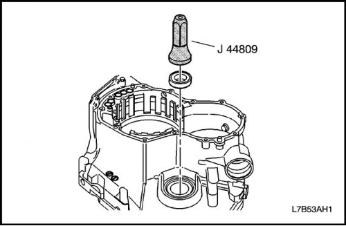
- Install the oil seal on the transaxle case side using J-44809.