Necessary equipment
- J-23327 Clutch Spring Compressor
- J-28585 Snap Ring Remover
- J-41236 Inertia Clutch Spring Compressor
- J-45164 Spring Compressor Bridge
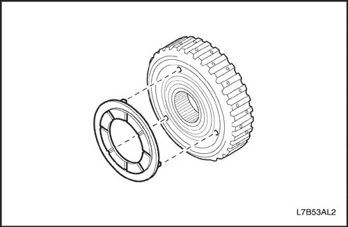
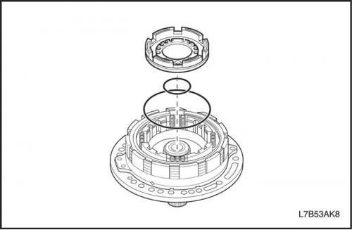
1. Install the 2nd gear brake piston (B2).
- Lubricate the new sealing rings with automatic transmission fluid and install them on the piston.
- Lubricate the inner surfaces of the oil pump cover with automatic transmission fluid.
- Press the piston into the oil pump cover.
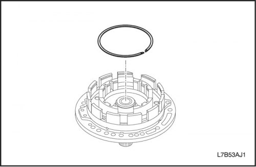
- Install the retaining ring.
Important: Be careful not to damage the oil pump cover.
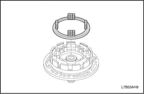
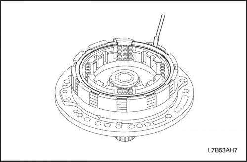
2. Install the 2nd gear brake return spring (B2).
- Install the return spring onto the piston with the spring side facing up.
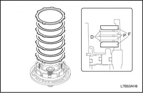
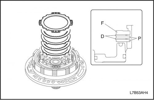
3. Install the 2nd gear brake plate, disc and flange (B2).
- Install the flange, disc and plate as shown in the figure.
Important: Make sure that the number and order of installation of plates and disks is correct.
Order: F-D-P-D-P-D-F (FAM II 2.4D)
P-D-P-D-P-D-P-D-F (HFV6 3.2L or 2.0S Diesel)
|
Clutch and brake
|
Flange (F)
|
Plate (P)
|
Disk (D)
|
|
2nd gear brake (B2)
|
2 (1)
|
2 (4)
|
3 (4)
|
- (): In case of HVF6 3.2L or 2.0S Diesel
- Using a screwdriver, install the retaining ring.
- Make sure that the cut of the retaining ring does not coincide with any of the notches.
4. Install the 2nd gear inertia brake piston (B1).
- Lubricate the sealing rings with automatic transmission fluid and install them on the piston.
- Lubricate the inner surfaces of the oil pump cover with automatic transmission fluid.
- Press the piston into the oil pump cover.
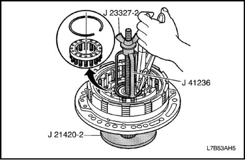
5. Install the 2nd gear inertia brake return spring (B1).
- Install J-21420-2 and J-23327-2, which is part of J-23327, and J-41236 onto the return spring and compress the spring.
- Using snap ring pliers, install the snap ring into the groove of the oil pump cover.
6. Install the 2nd gear overrun brake flange, disc and plate (B1).
- Install the flange, disc and plate as shown in the figure.
Important: Make sure that the number and order of installation of plates and disks is correct.
- Order: P-D-P-D-F (FAM II 2.4D)
- P-D-P-D-P-D-F (HFV6 3.2L or 2.0S Diesel)
|
Clutch and brake
|
Flange (F)
|
Plate (P)
|
Disk (D)
|
|
2nd gear inertia brake (B1)
|
1 (1)
|
2 (3)
|
2 (3)
|
- (): In case of HFV6 3.2L or 2.0S Diesel
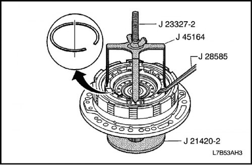
- Using J-45164, J-21420-2 and J-23327-2, which is part of J-23327, compress the spring.
- Using J-28585, install the retaining ring into the groove of the reactor shaft.
Caution: When working with compressed air, wear protective glasses to prevent eye injury.
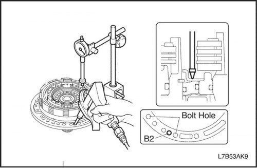
7. Check the stroke of the 2nd gear brake piston (B2).
- Install the indicator as shown in the figure.
- By supplying compressed air (4 kg/cm?) to the lubrication channel as shown in the figure, measure the piston stroke and make sure that the piston moves smoothly.
- Piston stroke: 1.10-1.50 mm (0.043-0.059 inches)
If the piston stroke is not within the norm, select another flange.
- Flange thickness type: 3.6mm (0.142 inches), 3.8 mm (0.150 inches), 4.0 mm (0.157 inches)

8. Check the piston stroke of the 2nd gear inertia brake (B1).
- Install the indicator as shown in the figure.
- By supplying compressed air (4 kg/cm?) to the lubrication channel as shown in the figure, measure the piston stroke and make sure that the piston moves smoothly.
- Piston stroke: 1.24-1.96 mm (0.049-0.077 inches)
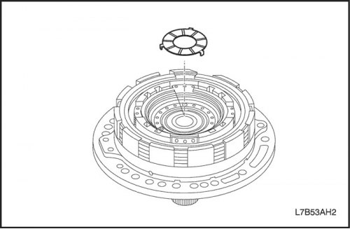
9. Install the thrust ring.
- Install the thrust ring with grease so that the flat surface faces up.