


Unscrew handle 5 (figure 3-8) from gearbox lever 6 and remove cover 7.
Loosen the bolts securing the front propeller shaft to the flanges of the front axle gearbox and transfer case and remove the front propeller shaft.
Disconnect the suspension of pipes and mufflers at the rear of the car, then the flange of the neutralizer from the inlet pipe and remove the neutralizer, additional and main mufflers in assembly. Bend the edges of the locking plates and unscrew the nuts securing the inlet pipe to the exhaust manifold. Remove the crankcase protection and the engine splash guard. Unscrew the oxygen sensor on the inlet pipe. Unscrew the nuts securing the stabilizer and remove the stabilizer. Unscrew the nut securing the inlet pipe to the support bracket and remove the inlet pipe downwards.
Disconnect the wires from the reverse light switch.
Disconnect the slave cylinder from the clutch housing. In this case, the cylinder connected to the pipeline leading to the master cylinder of the clutch release drive remains on the car, which eliminates the loss of brake fluid and the need for subsequent bleeding of the hydraulic clutch release drive.
Using a socket wrench, loosen the bolts securing the starter to the clutch housing and release it. Loosen the bolts securing the clutch housing cover.
Install the A.70025 clamping clamp on the flexible coupling and tighten it. This will facilitate the removal and subsequent installation of the flexible coupling. Unscrew the nuts and, turning the intermediate cardan shaft, remove the bolts securing the flexible coupling to the flange of the secondary shaft of the gearbox. Turning the intermediate cardan shaft, unscrew the nuts of the studs securing the shaft to the flange of the transfer case. Move the coupling in the splined connection of the shaft back relative to the flange of the gearbox until the centering ring comes out of the hole in the coupling and remove the intermediate cardan shaft.
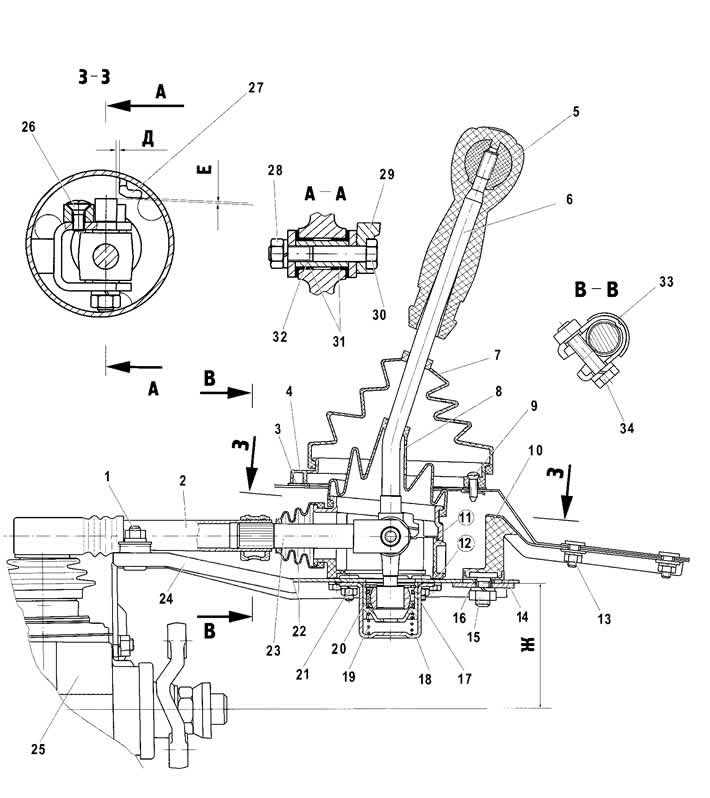
Figure 3-8. Gear selection mechanism control drive:
1 - support plate fastening nut;
2 - gearbox control drive rod;
3 - hatch cover gasket;
4 - Gear shift lever hatch cover;
5 - gear shift lever handle;
6 - gear shift lever;
7 - Gear shift lever cover;
8 - sealing cover;
9 - hatch cover fastening screw;
10 - rear support;
11 - gear shift lever housing;
12 - lower housing of the gear shift lever;
13 - rear support mounting nuts;
14 - rear support washer;
15 - nut;
16 - spacer ring;
17 - retaining ring;
18 - ball joint housing;
19 - gear shift lever spring;
20 - ball joint slider;
21 - Ball joint housing fastening nuts;
22 - protective cover;
23 - traction rod end;
24 - support plate;
25 - gearbox;
26 - screw for fixing the locking stop;
27 - reverse locking pad;
28 - nut of the tie rod end mounting bolt;
29 - locking stop;
30 - tie rod end mounting bolt;
31 - bushings;
32 - spacer sleeve;
33 - control drive rod clamp;
34 - clamp bolt.
Unscrew nut 15 connecting support plate 24 of the control drive with rear support 10.
Disconnect the rear engine mount support from the crossmember, then remove the crossmember while supporting the transmission from underneath.
Remove the gearbox control drive, for which:
- unscrew the three nuts securing the bracket to the rear cover of the gearbox 25;
- loosen the clamp mounting bolt 34 and disconnect the control drive rod;
- remove the gearbox control drive.
Place a jack, stands or other suitable support under the gearbox housing. Using a socket wrench, loosen the engine mounting bolts and remove the gearbox together with the clutch housing, moving it toward the rear of the car so as to remove the gearbox input shaft from the front bearing and from the driven disk hub.
Warning: When removing or installing the gearbox, do not rest the end of the input shaft on the petals of the clutch pressure spring, so as not to deform the clutch pressure spring.
The gearbox is installed in the reverse order of removal. Before installation, clean and wash the splines on the gearbox input shaft and the clutch driven disk hub with white spirit, center the clutch driven disk with the A.70081 mandrel (see figure 3-3).
After installation on the clutch housing, apply DT-1 grease to the spherical surface of the clutch drive cylinder pusher.
Check the level and, if necessary, add oil to the gearbox housing. The oil level should be up to the lower edge of the filler hole.
(Original version of the article on the website: CHEVYMAN.RU)