


Remove the clutch release fork and the clutch release sleeve assembly from the guide sleeve of the front gearbox cover.
Remove the clutch housing with the gasket and the front cover of the gearbox together with the oil seal and spring washer (see figure 3-9).
Unscrew the reversing light switch, being careful not to deform its housing.
Remove the bolt securing the shift fork for the third and fourth gears. Install the 41.7816-4070 locking pin on the primary shaft or engage two gears simultaneously. This will prevent the primary, secondary and intermediate shafts from turning and will allow subsequent disassembly operations to be performed.
Unscrew nut 28 (see figure 3-7) several turns to move the centering ring 30 of the elastic coupling, and tighten the nut 28 again. Use a puller to remove the centering ring of the elastic coupling of the cardan shaft from the end of the secondary shaft (figure 3-10).
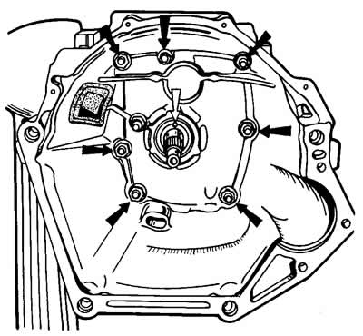
Figure 3-9. Clutch housing interior view
The black arrows indicate the nuts that secure the clutch housing to the gearbox; the white arrow indicates the hole in the front cover for releasing oil from the gearbox housing to prevent the clutch discs from becoming oily.
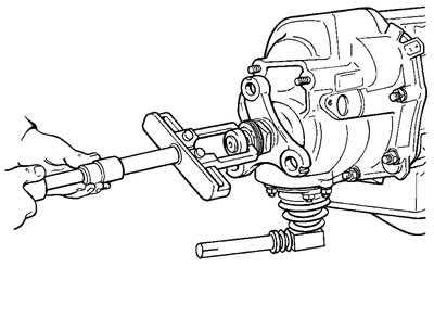
Figure 3-10. Removing the centering ring of the flexible coupling of the cardan shaft.
Remove the seal 29 of the centering ring of the elastic coupling from the end of the secondary shaft, unscrew the nut 28 and remove the flange of the elastic coupling using a puller (figure 3-11).
Before removing the rear cover, remove the gear selector mechanism. To do this, remove the drive rod clamp 33 (see figure 3-8), unscrewing bolt 34. Then, unscrewing fastening nuts 21 (see figure 3-7), remove the gear selector mechanism assembly.
Unscrew the six nuts securing the rear cover 36, and one of the nuts securing the rear cover is unscrewed from inside the gearbox housing with the lower cover removed. When removing the rear cover, it must not only be fed back, but also turned to prevent it from touching the reverse gear block and fifth gear.
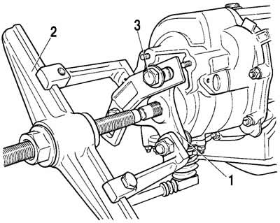
Figure 3-11. Removing the flexible coupling flange with a puller:
1 - elastic coupling flange;
2 - puller;
3 - bolts for fastening the puller to the flange.
After removing the inner ring of the rear bearing 32 and the spacer sleeve 33 of the bearing from the secondary shaft, loosen the bolts securing the cover of the retainers 5 (figure 3-12) and unscrew bolts 2 and 4 securing the gear block and the fifth gear and reverse gear engagement fork. Remove oil deflector washer 26 (see figure 3-7) and remove rod 1 (figure 3-13) from fork 2. At the same time, the spacer sleeve 3 is removed from the rod. Then remove the gear block 4 from the splines of the intermediate shaft.
Remove intermediate gear 1 at the same time (figure 3-14) reverse gear from the axle, gear 3 assembled with the clutch and fork 4 from the secondary shaft. Then remove the thrust washer and retaining ring.
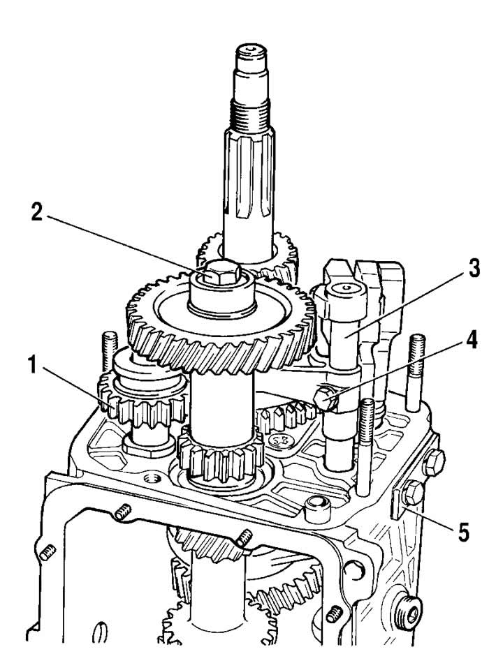
Figure 3-12. Unscrewing the bolts securing the gear block and the 5th gear and reverse gear engagement fork:
1 - intermediate reverse gear;
2 - gear block mounting bolt;
3 - fork stem;
4 - fork mounting bolt;
5 - cover of the clamps.
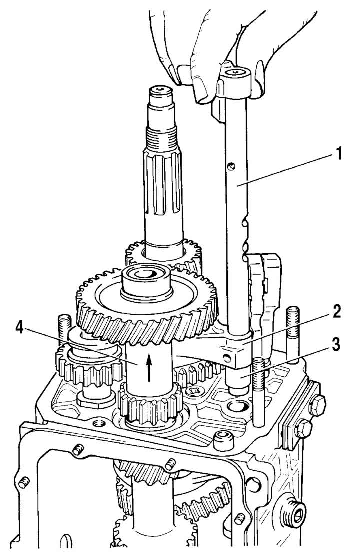
Figure 3-13. Removing the 5th gear and reverse gear fork rod:
1 - rod for engaging the 5th gear and reverse gear;
2 - fork for engaging V gear and reverse gear;
3 - spacer sleeve;
4 - gear block.
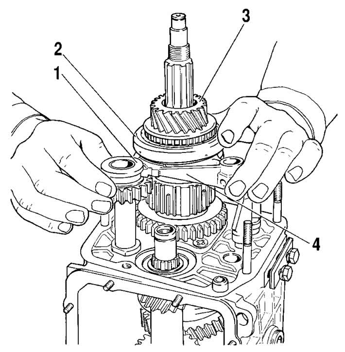
Figure 3-14. Removing the reverse intermediate gear, the 5th gear assembly with the synchronizer and fork:
1 - intermediate reverse gear;
2 - 5th gear engagement clutch;
3 - V gear and reverse gear;
4 - fork for engaging 5th gear and reverse gear.
Remove hub 4 (figure 3-15) synchronizer of the fifth gear, spring washer and driven gear 2 of reverse gear.
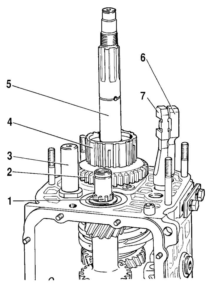
Figure 3-15. Removing the reverse driven gear and the 5th gear synchronizer clutch hub:
1 - intermediate shaft;
2 - reverse driven gear;
3 - reverse intermediate gear axis;
4 - hub of the 5th gear synchronizer clutch;
5 - secondary shaft;
6 - rod for the fork for engaging 1st and 2nd gears;
7 - fork rod for engaging III and IV gears.
Using shaped mandrels and rod punches, remove the front and rear intermediate shaft bearings from the gearbox housing. Mark the inner rings of the double-row bearing with the help of which you install these rings in their previous places in the outer ring of the bearing.
Remove the intermediate shaft from the gearbox housing by tilting it as shown in Figure 3-16.
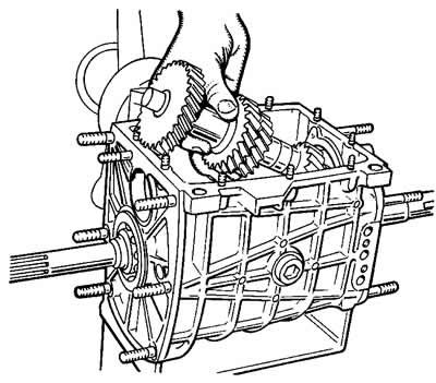
Figure 3-16. Removing the intermediate shaft from the gearbox housing.
Remove the shift fork rods of the first, second, third and fourth gears from the gearbox housing one by one, after first unscrewing the fork mounting bolts. While removing the rods, simultaneously remove the three locking crackers 6 (figure 3-17). Remove the locking plate (figure 3-18) intermediate bearing of the secondary shaft. Unscrew the nut securing the axle of the intermediate reverse gear gear and remove it.
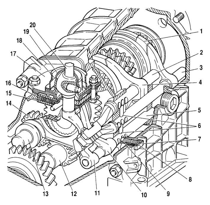
Figure 3-17. Gear selection drive:
1 - fork for engaging III and IV gears;
2 - rod for the fork for engaging 1st and 2nd gears;
3 - fork rod for engaging III and IV gears;
4 - fork for engaging 1st and 2nd gears;
5 - V gear and reverse gear fork rod;
6 - locking crackers;
7 - cover of the clamps;
8 - spring of the clamps;
9 - ball of the locks;
10 - fork for engaging V gear and reverse gear;
11 - head of the fork rod for engaging V gear and reverse gear;
12 - block of gears of the 5th gear and reverse gear;
13 - reverse intermediate gear axle;
14 - reverse intermediate gear;
15 - guide plate washer;
16 - guide plate;
17 - gear selector lever housing;
18 - ball joint;
19 - spherical washer of ball joint;
20 - gear selection lever.
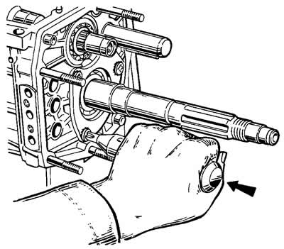
Figure 3-18. Loosening the screws securing the secondary shaft intermediate bearing lock plate using a drill-screwdriver.
The arrow shows the direction of the impact stroke of the screwdriver clip when struck with a hammer.
Using drifts, remove the primary shaft together with the bearing and synchronizer ring (figure 3-19) and remove the needle bearing from the front end of the secondary shaft.
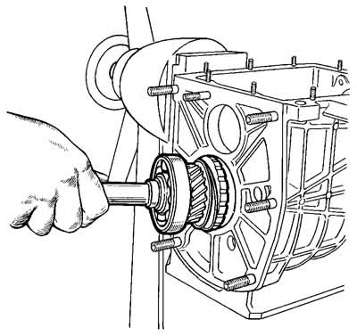
Figure 3-19. Removing the input shaft from the gearbox housing.
Knock the secondary shaft out of the intermediate bearing, remove the intermediate bearing and, tilting it as shown in Figure 3-20, remove the secondary shaft from the crankcase complete with gears, couplings and synchronizer rings. Remove the synchronizer coupling of III and IV gears from the shaft.
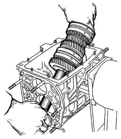
Figure 3-20. Removing the secondary shaft from the gearbox housing.
Disassemble the primary shaft (figure 3-21):
- remove the retaining ring 7, the locking ring 6 and the synchronizer spring 5;
- install the shaft on the press and, having compressed the spring washer 2 with the mandrel 41.7816-4069, remove the retaining ring 1, and then the spring washer and bearing 3.
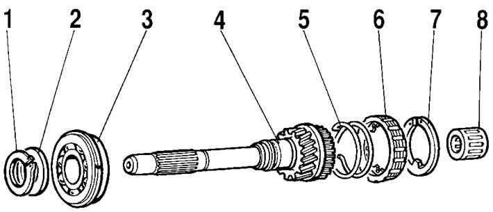
Figure 3-21. Primary shaft parts:
1 - retaining ring;
2 - spring washer;
3 - bearing;
4 - primary shaft;
5 - synchronizer spring;
6 - synchronizer locking ring;
7 - retaining ring;
8 - bearing.
Disassemble the secondary shaft (figure 3-22):
- remove gear 11 of the first gear with sleeve 12, hub 3 with sliding clutch 4 for switching 1st and 2nd gears, gear 10 of the second gear together with locking ring 5 of the synchronizer from the rear side of the shaft;
- install the secondary shaft with the mandrel 41.7816-4069 on the press (figure 3-23), place support half rings 3 under the third gear pinion and, pressing the mandrel onto the spring washer, remove the retaining ring 2, then the spring washer 4, the hub of the sliding clutch for switching third and fourth gears and the third gear pinion.
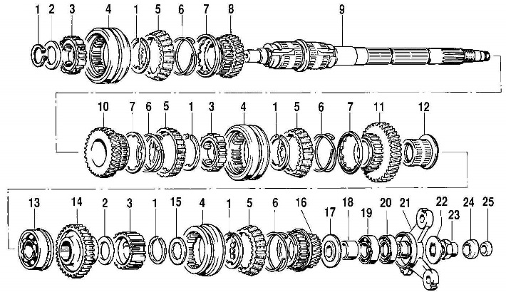
Figure 3-22. Secondary shaft parts:
1 - retaining ring;
2 - spring washer;
3 - synchronizer hub;
4 - synchronizer clutch;
5 - blocking ring;
6 - synchronizer spring;
7 - washer;
8 - gear of the 3rd gear;
9 - secondary shaft;
10 - 2nd gear pinion;
11 - 1st gear pinion;
12 - gear bushing;
13 - bearing;
14 - reverse gear;
15 - thrust washer;
16 - V gear;
17 - oil deflector washer;
18 - spacer sleeve;
19 - secondary shaft rear bearing;
20 - oil seal;
21 - elastic coupling flange;
22 - lock washer;
23 - nut;
24 - seal;
25 - centering ring.
If necessary, disassemble the gear selector mechanism (figure 3-24), for what:
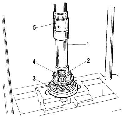
Figure 3-23. Installing the retaining ring on the secondary shaft:
1 - mandrel 41.7816-4069;
2 - retaining ring;
3 - support half ring;
4 - spring washer;
5 - press rod.
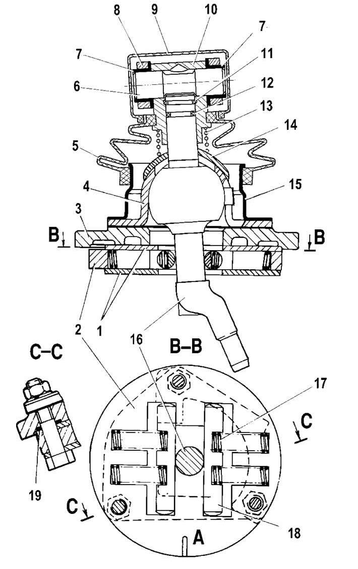
Figure 3-24. Gear selection mechanism:
1 - guide plate washer;
2 - guide plate;
3 - gear selector lever housing;
4 - ball joint;
5 - front hinge housing cover;
6 - traction hinge axis;
7 - tie rod eye bushing;
8 - gearbox control drive rod;
9 - control drive rod cover;
10 - control drive rod hinge housing;
11 - retaining ring;
12 - sealing ring;
13 - gear selector lever spring;
14 - spherical washer of ball joint;
15 - flange;
16 - gear selection lever;
17 - guide bar spring;
18 - guide bar;
19 - sealing ring;
A - risk.
- remove protective covers 1 and 6 (figure 3-25);
- pull the housing of the traction joint 3, squeezing the retaining ring 15, from the gear selection lever 13.
This will allow you to remove the hinge pin of the rod 2 and remove the drive rod 5 with two bushings 4
- remove spring 21 and spherical washer of ball joint 22 from gear selection lever 13;
- visually mark the location of the parts relative to mark A (see figure 3-24), applied to the guide plate to ensure that the parts are connected in the same position during assembly;
- after unscrewing the nuts from the mounting bolts, separate the parts of the gear selection mechanism and remove lever 16, its ball joint 4 and sealing rings 19.
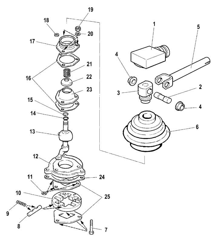
Figure 3-25. Gear selection mechanism parts:
1 - front traction cover;
2 - traction hinge axis;
3 - traction joint housing;
4 - tie rod eye bushing;
5 - gearbox control drive rod;
6 - front hinge housing cover;
7 - bolt;
8 - guide bar;
9 - guide bar spring;
10 - guide plate;
11 - sealing ring;
12 - gear selector lever housing;
13 - gear selection lever;
14 - sealing ring;
15 - retaining ring;
16 - Ball joint gasket;
17 - seal mounting flange;
18 - washer;
19 - nut;
20 - washer;
21 - spring;
22 - spherical washer of ball joint;
23 - ball joint of gear selector lever;
24 - gasket;
25 - guide plate washer.
Also, if necessary, disassemble the gear selection mechanism control drive, for which:
- remove protective cover 12 (figure 3-26), remove the reverse gear lock lining 24 from the lever housing by unscrewing the two bolts 25;
- disassemble the gear selector lever housing by unscrewing four bolts 35;
- remove the ball joint housing 1 by unscrewing the three nuts 37. Then unscrew the nut 23, remove the gear selection lever shaft 15 and remove the tie rod end 13;
- to remove the ball joint slider 3, remove the retaining ring 4.
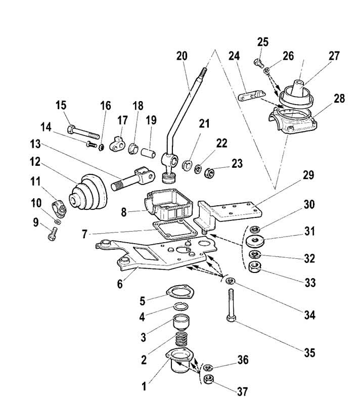
Figure 3-26. Gear Selector Control Drive Parts:
1 - ball joint housing;
2 - spring;
3 - ball joint slider;
4 - retaining ring;
5 - ball joint housing gasket;
6 - support plate;
7 - lower housing gasket;
8 - lower housing of the gear selector lever;
9 - clamp bolt;
10 - washer;
11 - control drive rod clamp;
12 - protective cover;
13 - traction rod end;
14 - locking stop screw;
15 - gear selector lever axis;
16 - toothed washer;
17 - locking stop;
18 - bushing;
19 - spacer sleeve;
20 - gear selector lever;
21 - bushing;
22 - washer;
23 - lever axle nut;
24 - reverse gear locking pad;
25 - lining bolt;
26 - washer;
27 - sealing cover;
28 - gear selector lever housing;
29 - rear support;
30 - spacer ring;
31 - rear support washer;
32 - washer;
33 - rear support nut;
34 - washer;
35 - Gear selector lever housing bolt;
36 - washer;
37 - ball joint housing fastening nut.
Assemble the gearbox in the reverse order of disassembly. Please note that:
- the reverse intermediate gear shaft is secured before installing the shafts in the gearbox housing with a torque of 70...80 Nm (7...8 kgf·m);
- before installing the fifth gear and reverse gear fork rod into the crankcase, install a spacer sleeve on it;
- the inner bearing ring is pressed onto the fifth gear and reverse gear block, and the outer one is pressed into the rear cover socket;
- the secondary shaft rear bearing is pressed onto the shaft to facilitate installation of the rear cover;
- intermediate gear 1 (see figure 3-14) reverse gear, gear 3 and fork 4 install simultaneously;
- tighten the gear block mounting bolt to a torque of 70.80 Nm (7.8 kgf·m);
- before installation, coat the working surface of the seals with Litol-24 grease;
- when installing seals and bearings, use mandrels 41.7853-4028, 41.78534032, 41.7853-4039;
- when assembling the gear selection mechanism, apply Litol-24 or LSC-15 grease to the surfaces of the gear selection lever that contact the ball joint and the traction joint housing. Also apply grease to the inner surface of the spherical washer of the ball joint;
- when assembling the gearshift control drive, apply LSC-15 grease to the inner surface of the ball joint housing;
- when installing the gearshift control drive, holding the gearshift lever and the support plate in a relative position determined by the dimensions (see figure 3-9) D= (1.5+0.5) mm, E=(1+0.5) mm and W=(81.5+0.5) mm, tighten the control drive rod clamp bolt to a torque of 16...25 N·m (1.6...2.5 kgf·m);
- when installing the gear selector handle, ensure that it is positioned relative to the direction of travel of the vehicle as shown in Figure A (figure 3-27).
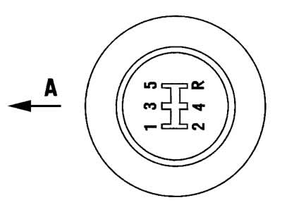
Figure 3-27. Installing the gear selector lever handle:
A - direction of vehicle movement.
The original text can be found on the website: «ChevyMan»