
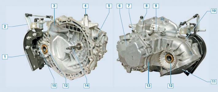
Chevrolet Lacetti five-speed manual transmission: 1 — powertrain rear support bracket; 2 — gearbox control drive; 3 — clutch housing; 4 — breather (filler plug); 5 - Reverse light switch; 6 - back cover; 7 — lock for adjusting the gearbox control drive; 8 — gear shift cover; 9 — gear shift mechanism rod; 10 — speed sensor drive (not visible in the photo); 11 - bottom cover; 12 — front wheel drive oil seal; 13 — intermediate crankcase; 14 — primary shaft; 15 — oil level inspection hole plug.
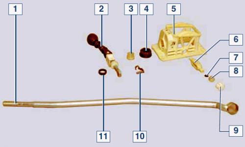
Elements of the gear shift control mechanism: 1 — control rod; 2 - gear shift lever; 3 — rod guide bushing; 4 — damper; 5 — mechanism body; 6 — wings; 7 — bearing buffer; 8 — gear shift bearing; 9 — bearing support; 10 — lever axis; 11 — lever support washer
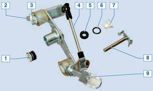
Gear shift drive elements: 1 - bearing; 2 — input shaft; 3 — rocker arm; 4 - traction; 5 — bearing damper; 6 - sealing ring; 7 — bearing sleeve; 8 - rocker axis; 9 — output shaft
The mechanical gearbox is two-shaft, with five forward gears and one reverse gear, with synchronizers on all forward gears. The gearbox is structurally combined with the differential and final drive.
The gearbox housing consists of three parts cast from aluminum alloy: a housing combined with a clutch housing, an intermediate housing and a rear cover.
The primary shaft has a dismountable design, on it on splines a block of leading gears of 1-4 gears, as well as a leading gear of 5 gear. All leading gears are in constant engagement with the corresponding driven gears of the forward gears. The gears are cylindrical, helical, with the exception of straight-toothed gears of the reverse gear.
The secondary shaft is hollow (for supplying oil to the driven gear bearings). It contains driven gears, forward gear synchronizers, and the main gear drive pinion, which is integral with the shaft. Each driven gear has an additional straight-toothed crown, with which the synchronizer sliding clutch is connected when the gear is engaged. The front shaft bearings are roller bearings, and the rear ones are ball bearings. Roller bearings withstand large radial loads, while ball bearings withstand both radial and axial loads that arise when a pair of helical gears mesh. The shafts are held from axial movement by ball bearings installed in the intermediate housing.
The differential is bevel, two-satellite. The preload in the bearings is adjusted by turning the bearing adjusting nut (from the left drive side). The driven gear of the main transmission is bolted to the differential box flange. Two satellites and two axle gears are installed in the differential box.
The satellites are mounted on an axle secured in the differential box. The semi-axle pinions are mounted on the inner hinges of the wheel drives, which are fixed in the gears by split spring rings.
The cylindrical surfaces of the tailpieces are fitted with seals pressed into the clutch housing sockets.
To prevent water from entering and reduce dust from entering the gearbox cavity, its breather is installed in the upper part of the gearshift mechanism housing. Oil can be poured into the gearbox by unscrewing the breather.
The gear shift lever is mounted on the floor tunnel in the plastic housing of the control mechanism and is connected to the control rod.
The other end of the control rod is connected via a drive to the gear shift mechanism located in the gearbox.
At the factory, the gearbox is filled with transmission oil designed to last the entire service life of the vehicle.
The oil level in the gearbox should be at the level of the lower edge of the inspection hole.
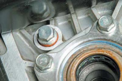
Location of the oil level inspection plug in the gearbox (for clarity, the right wheel drive has been removed)
There is no drain hole in the gearbox, so if you need to drain the oil from the gearbox, you will need to remove the bottom cover.
For operations on replacing the gearbox primary shaft seal, see. Removal the hydraulic drive slave cylinder assembly and clutch release bearing.
[The article is based on data from the website: ChevyMan.ru]