


Remove the battery (see Removal the battery). Loosen the tightening of the bolt of the terminal connection of the gearbox control rod with the input shaft of the drive (see Adjusting the gearbox control drive), we remove the drive shaft from the rod hole.
Disconnect the wiring harness from the reverse light switch (see Removal the reverse light switch). Remove the vehicle speed sensor (see Removal the vehicle speed sensor and its drive).
Remove the clutch hydraulic hose adapter from the tip of the clutch slave cylinder tube (see Replacing the clutch hydraulic hose).
In this case, to avoid leakage of working fluid from the reservoir of the brake and clutch hydraulic drives, we pinch the clutch hydraulic drive hose or insert a plug into the outlet of the hose adapter.
Remove the left mudguard from the engine compartment (see Removal the engine compartment mudguards).
Drain the oil from the gearbox (see Gearbox oil change). Remove the front wheel drives (see Removal the front wheel drives).
We place a height-adjustable stop under the engine oil pan, placing a wooden spacer underneath.
Remove the rear support of the power unit (see Replacing the powertrain mounts).
The gearbox can be dismantled together with the gear shift drive or by first removing it.
We remove the gear shift mechanism drive assembly with the power unit rear support bracket. To do this, we disconnect the forks of the drive output shaft and the gear shift mechanism rod (see Removal the gearshift drive), and then…
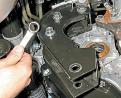
…using a 17 mm open-end wrench, unscrew the three bolts securing the bracket to the clutch housing.
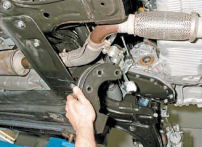
We remove the rear support bracket of the power unit together with the gear shift drive.
Before unscrewing the bolts securing the clutch housing to the engine cylinder block, mark their location. This will simplify subsequent installation of the gearbox, since the bolts securing the clutch housing are different in diameter and rod length.
At the top, the clutch housing is attached to the cylinder block with three bolts.
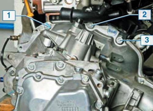
For clarity, we show the location of the bolts for the upper mounting of the clutch housing on the dismantled power unit.
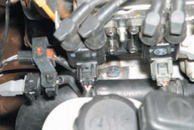
Bolt 1, located under the ignition coils…
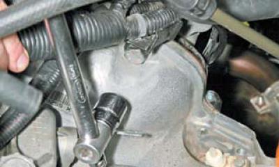
…and bolt 3, which also secures the wiring harness bracket, is unscrewed with a 19 mm head.
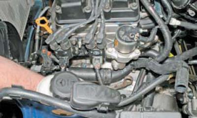
Unscrew bolt 2, located under the coolant pump supply pipe, using a 19 mm Z-key.
The coolant pump supply pipe prevents the operation of unscrewing bolt 2. To make the pipe mobile…
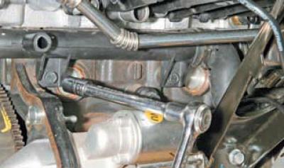
...from the rear side of the engine, using a 10 mm socket head, loosen the bolt that secures its left mount to the cylinder block (for clarity, shown on a dismantled engine).
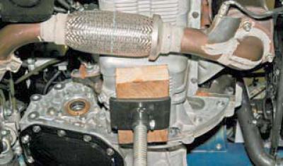
From the side of the engine oil pan, use a 19 mm head to unscrew the two bolts of the lower fastening of the clutch housing to the cylinder block, and use a 14 mm head to unscrew the three bolts of the lower fastening of the clutch housing to the oil pan.
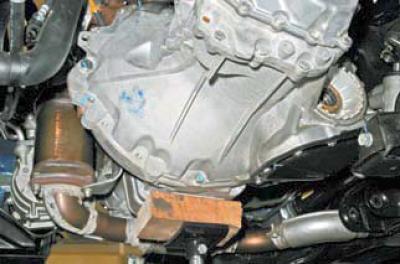
From the gearbox side, use a 19 mm head to unscrew another bolt of the lower fastening of the clutch housing to the cylinder block, and use a 14 mm head to loosen the bolt of the lower fastening of the clutch housing to the engine oil pan.
Having unscrewed the nuts and the bolt securing the base of the fuse and relay mounting block in the engine compartment, we move the block away from the left support of the power unit, without disconnecting the wiring harness connectors from the block (see Replacing the powertrain mounts).
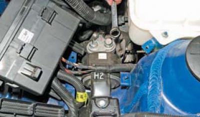
Using a 19 mm open-end wrench or socket, unscrew the nut and bolt securing the adapter of the left support of the power unit to the support bracket.
We lower it on an adjustable stop (placed under the engine oil pan) power unit, removing the pin of the left support bracket of the power unit from the hole in the support adapter.
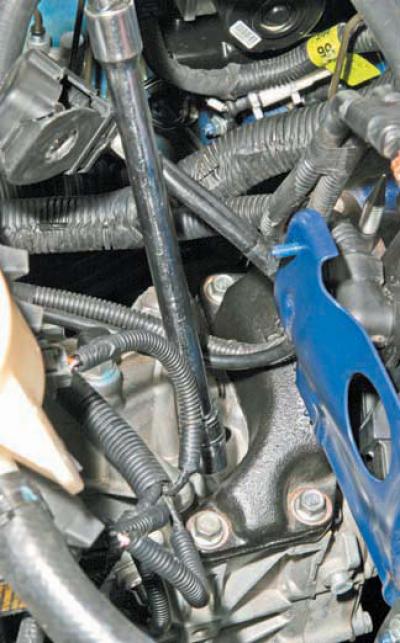
Using a 14 mm socket with an extension, unscrew the three bolts securing the left powertrain support bracket to the clutch housing…
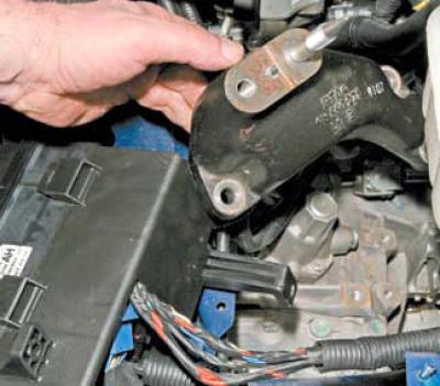
and remove the support bracket.
To facilitate removal of the gearbox (weighs more than 20 kg), we install another adjustable stop under the clutch housing and completely unscrew it (from the gearbox side) bolt of the lower fastening of the clutch housing to the engine oil pan.
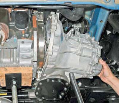
We move the gearbox away from the engine to the left side member.
We lower the gearbox on an adjustable stop..
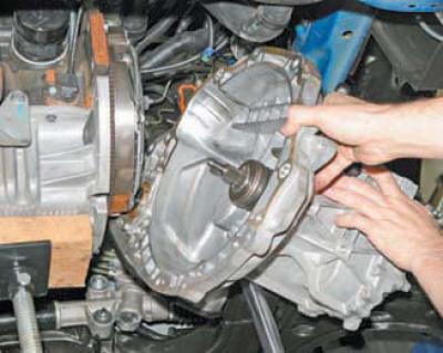
…and we take it off.
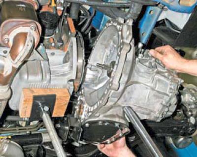
The gearbox can also be removed without disconnecting the gearshift drive and the rear powertrain support bracket.
When removing or installing the gearbox, do not rest the input shaft of the gearbox on the petals of the diaphragm spring of the clutch basket, so as not to damage them.
Before installing the gearbox, apply a thin layer of plastic grease, for example, SHRUS-4, to the splined part of the primary shaft.
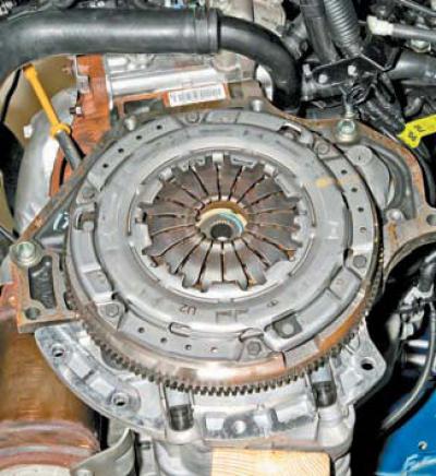
We check the condition of the two centering bushings pressed into the holes of the cylinder block.
If the bushings are missing or deformed, new ones must be installed.
We install the gearbox in the reverse order.
After inserting the primary shaft of the gearbox into the splined hole of the driven clutch shaft, we send the gearbox to the right until the mating surfaces of the clutch housing, cylinder block and engine oil pan are in full contact. We screw in and tighten all the clutch housing mounting bolts. We install the power unit supports. We finally tighten the clutch housing mounting bolts to the required torques in the following sequence: - tighten the three lower mounting bolts to the cylinder block to a torque of 72–74 N·m; - one bolt of the lower mount to the engine oil pan (next to the hole in the clutch housing under the right front wheel drive) — torque 30–32 Nm; — three more bolts for the lower mount to the engine oil pan — torque 20–22 N·m.
— tighten the three upper mounting bolts to the cylinder block to a torque of 72–74 N·m.
After installing the gearbox, we fill it with oil, adjust the gear shift drive, and bleed the clutch hydraulic drive.
[The original source of the article is the website «chevyman»]