
Warning: The vehicles described in this manual are equipped with a Supplemental Restraint System (SRS), also known as an air bag system. Before carrying out work in the area where the elements of this system are located, it is necessary to disconnect its power supply, since accidental deployment of the airbags can result in serious injury (see chapter 12).
1. The front and rear bumpers on the models described are a structure made of a plastic facing panel, which is located above a rigid metal beam.
Front bumper
2. If necessary, disconnect the fog light and turn signal connectors.
3. Remove the radiator grille as described in subsection 9.
Chevrolet and GMC cars
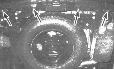
4. Remove the bolts and plastic pins that secure the bumper trim panel to the front body panel (see illustrations). Some fasteners are accessible from under the trim, while others are accessible from below the bumper.
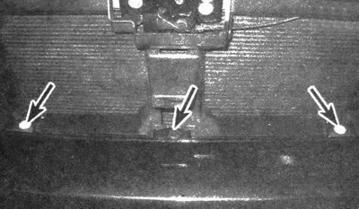
12.4a. Remove the bolts and pins located on top of the panel...
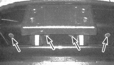
12.4b....and below it
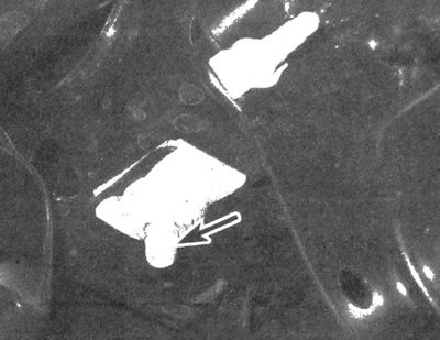
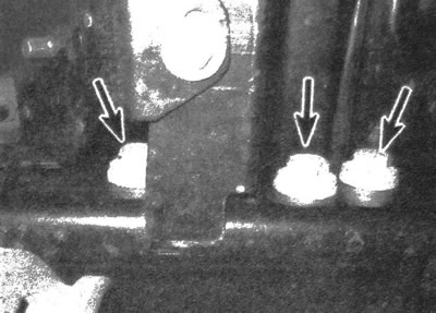
5. Performing the procedure from under the vehicle, remove the pins that secure the bumper trim to the reinforcement rods (see illustration).
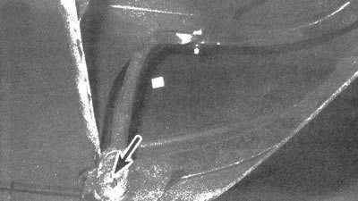
12.5. To detach the bumper trim from the reinforcement rods, remove the pins located at the bottom
Oldsmobile cars
6. Remove the bolts that secure the bumper trim to the front body panel from above.
7. Performing the procedure from under the vehicle, remove the pins that secure the bumper trim to the reinforcement rods (see illustration 12.5).
8. Remove the four pins that secure the bumper trim to the air deflector.
All models
9. Disconnect the clips located on each side of the bumper from the protrusions on the body (see illustrations). Pull forward and remove the bumper trim.
12.9. Disconnect the trim clips located on each side of the bumper
10. Unscrew the bolts and remove the bumper trim reinforcement pins from the rigid beam.
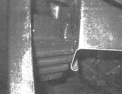
11. Ask an assistant to support a rigid beam, unscrew the bolts securing it to the frame and remove the element (see illustration).
12.11. Unscrew the bolt located on each side and remove the bumper rigid bar
12. Disconnect the wiring and other elements that prevent removal, and remove the bumper from the vehicle.
13. Installation is carried out in the reverse order of removal. Tighten the mounting bolts to the required torques.
Rear bumper
14. Disconnect the reverse light wiring.
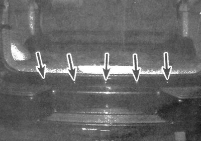
15. Remove the pins located at the bottom of the bumper trim (see illustration).
12.15. Remove the pins located at the bottom of the rear bumper trim
16. Remove the screws that secure the bumper trim panel to the wheel arches on each side (see illustration).
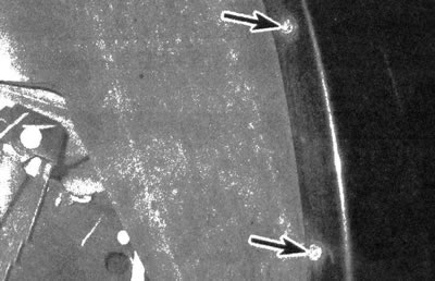
12.16. Remove the screws that secure the bumper trim panel to the wheel arches on each side
17. Unscrew the bolts securing the upper edge of the bumper trim to the body and remove it from the car (see illustration).
2.17. Unscrew the bolts located along the upper bumper trim
18. If the rigid bar is to be removed, remove the spare wheel carrier. Disconnect the harness from the trailer wiring connector, turn the connector counterclockwise and remove it from the vehicle body.
19. Unscrew two of the three beam mounting bolts located on each side (see illustration).
12.19. Unscrew the bolts of the bumper rigid bar
20. Ask an assistant to support the beam and unscrew the only remaining mounting bolt on each side. Remove the bumper stiffener from the vehicle.
21. Installation is carried out in the reverse order of removal. Tighten the mounting bolts to the required torque.
The source of the article is available on the website: CHEVYMAN.RU