
Contents: Airbags ↧ Sensing/diagnostic module and sensors ↧ System operation ↧ Self-diagnosis system ↧ Components located near the SRS… ↧ System shutdown ↧ Turning on the system ↧ Removal and installation ↧
1. All models covered by this manual are equipped with a supplemental restraint system (SRS), also known as an air bag system. The purpose of the system is to protect the driver and front seat passenger from serious injury in the event of a frontal or side collision. Side airbags located in the front seatbacks are standard equipment. They are only activated when there is a side impact of sufficient force. The design of all the described vehicles provides for the presence of an electronic unit of the SRS system, which is located under the rear part of the central console (see illustrations).
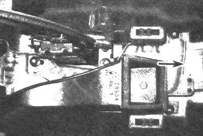
28.1 The SRS control unit is located under the rear of the instrument panel - do not touch the connectors connected to it
Warning: If the vehicle has been flooded or the upholstery has been soaked with water for any other reason, the battery must be disconnected and the engine must not be started until the system has been checked at an authorized service station. If the SRS system components are exposed to intense moisture, the airbags may deploy immediately after the engine is started, even if the vehicle has not been subjected to an impact.
Airbags
2. The airbag unit is a chamber with an inflation device, which are located in a single housing. The airbag inflator is located at the rear of the housing and is connected to a hole through which air is forced into the chamber, instantly filling it when a pulse is received from the crash sensor. The impulse is sent to the driver's airbag unit via a slip ring installed under the unit in the steering wheel. The slip ring is a flat tape that has electrical conductivity. The signal to the airbag unit can be sent at any position of the steering wheel. The airbags are located in the steering wheel, in the instrument panel above the glove compartment, and in the backrests of the front seats (side airbags).
Sensing/diagnostic module and sensors
3. The module includes a microprocessor of the on-board system, due to the presence of which automatic control of the SRS system is carried out. The module also contains a shock sensor. The system is diagnosed every time the engine is started. If there is no malfunction in the system, the "AIRBAG" indicator flashes seven times and then turns off. If there is a fault in the system, the indicator may not turn on at all, or may work continuously after turning on in an intermittent or continuous mode. A diagnostic code will be recorded in the electronic memory of the microprocessor, which will determine the cause of the malfunction.
4. There are two impact sensors located on the back side of the radiator support. The side airbags are linked to impact sensors located behind the front door panels and attached to the interior stiffeners.
System operation
5. The airbag is deployed when sensors located on the vehicle body and in the sensitive module are activated. When an impact of a certain force and direction occurs, the circuit of the inflator closes and the cushion deploys.
If the battery is damaged in an accident or the pump power is reduced for some other reason, the system is activated by an internal backup source.
Self-diagnosis system
6. The operation of this system is indicated by the indicator on the instrument panel when the ignition switch is turned to the ON position. If the system is working properly, the indicator flashes approximately seven times and then turns off. If the indicator does not come on, or does not go off within the normal short period of time, or if it comes on intermittently or continuously while driving, there is a malfunction in the SRS system. Contact your authorized service center immediately to have the problem fixed. Do not attempt to repair the SRS system yourself, as even the slightest mistake may result in the airbags not deploying at a critical moment.
Components located near the SRS system components
7. Sometimes it is necessary to remove the steering wheel or car radio, and also to service elements located near the instrument panel or other elements of the SRS system. Thus, it is necessary to carry out work in areas adjacent to the elements or wires of the passive safety system. Do not connect electrical testers to the SRS system wires as this may cause the airbags to deploy. Before working in the area adjacent to the wiring or components of the SRS system, it is necessary to disconnect the power supply to the system.
System shutdown
Warning: Before working in the area around SRS wiring or components, turn off the power to the SRS system.
8. Disconnection is carried out as follows:
- a) Set the wheels in the straight-ahead direction and turn the ignition switch to the LOCK position, then remove the key.
- b) Remove the SRS fuse located in the interior unit on the left side of the instrument panel.
- c) Wait for two minutes until the system's reserve power supply is exhausted.
- d) Remove the bumper located at knee level on the driver's side (see chapter 11) and disconnect the driver's airbag connector located on the steering column (see chapter 10).
- e) Open and lower the glove compartment door (see chapter 11), then disconnect the passenger airbag connector (see illustration).
- f) To deactivate the side airbag, remove the corresponding door trim (see chapter 11) and disconnect the side impact sensor connector.
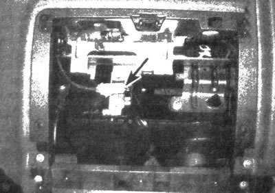
28.8. Disconnect the passenger airbag connector located behind the glove box
Turning on the system
9. Switching on is done as follows:
- a) Turn the ignition switch to the LOCK position, then remove the key.
- b) Connect the driver and passenger airbag connectors (or side airbag connector). Make sure of that. that the connectors are secured with clamps. because otherwise they may spontaneously detach.
- c) Install the SRS fuse.
- d) Turn the ignition switch to the ON position. Make sure that the system warning indicator flashes for 6-8 seconds and then turns off - this confirms that there is no fault in the system.
Removal and installation
Warning: When carrying the air spring unit, turn the side with the trim away from you. Store this item in a safe, isolated location with the finished surface facing up.
Driver's air bag
10. Disable the SRS system as described in paragraph. 8. The procedures for removing and installing the driver's airbag are described in Chapter 10.
Passenger air bag
11. Disable the SRS system as described in paragraph. 8.
12. Remove the glove box (see chapter 11). Remove the service cover located on the right side of the instrument panel and, having access through the opened hole, unscrew the bolts of the air outlet line and move it to the side.
13. Unscrew the lower mounting bolts and unscrew the upper nuts (which are located on each side of the air spring unit and point forward; access to the fasteners is available from under the instrument panel), then carefully remove the airbag from the instrument panel (see illustration).
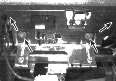
28.13. Unscrew the bolts (marked with lower arrows)and nuts (marked with upper arrows; invisible) fasteners and remove the passenger airbag from the dashboard
Caution: The airbag weighs more than you might think when looking at it; when removing from the instrument panel, it is necessary to support this unit with both hands.
14. Installation is carried out in the reverse order of removal.
Side air bags
15. Some models have side airbags, which are located on the sides of the front seat backs. Replacing these units requires disassembling the seats, so this procedure should be entrusted to specialists from a branded or other qualified station.
[The article was borrowed from the website «ChevyMan»]