


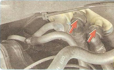
The heater radiator is connected to the engine cooling system by two hoses running through the engine compartment and is placed in a plastic casing of the climate control unit, installed under the central part of the instrument panel.
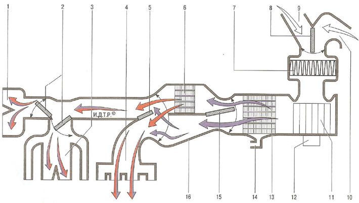
Fig. 12.1. Schematic diagram of air flow in the ventilation, heating and air conditioning system: 1 - windshield blower deflectors; 2 - air flow distribution flaps to the windshield deflectors and instrument panel deflectors; 3 - instrument panel deflectors; 4 - air ducts for heating the driver's and passengers' footwells; 5 - air flow distribution flap to the instrument panel deflectors and heating air ducts for the driver and passenger footwells; 6 - heater radiator; 7 - cabin air filter; 8 - air recirculation system damper; 9 - air intake box; 10 - air intake in the car interior; 11 - fan impeller; 12 - Fan motor; 13 - air conditioner evaporator; 14 - drainage hole for condensate draining; 15 - temperature regulator flap; 16 - heating and air conditioning system unit housing
Main components of the heater (Fig. 12.1):
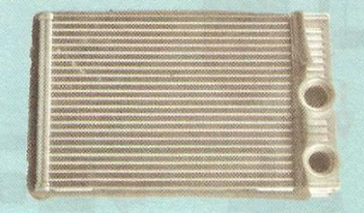
- heat exchanger (radiator) 6 heater, designed to heat the air entering the passenger compartment with the heat of the engine cooling liquid;
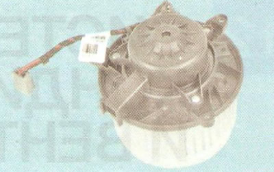
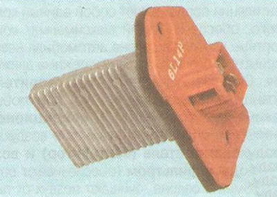
- fan (air blower) 11. Electric motor 12 of the fan with excitation from permanent magnets provides adjustable supply of outside air to the heater and air conditioner flaps. To obtain different values of the fan speed, a block of additional resistors is installed in the power supply circuit of the electric motor;
- air temperature regulator flap 15, coming from the heater into the passenger compartment. The amount of air passing through the heater heat exchanger and outside air bypassing the heat exchanger depends on the change in its position;
- air distribution flaps 2, coming from the heater through the air ducts into the passenger compartment or for blowing the windshield.
[The original text can be found on the website ChevyMan]