


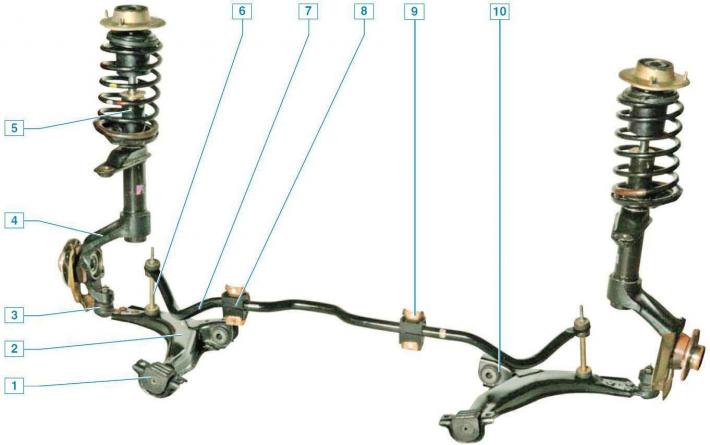
Front suspension: 1 — lever cushion; 2 - lever; 3 — ball joint; 4 - steering knuckle with hub; 5 — shock absorber strut; 6-crossbar stabilizer bar; 7 - crossbar stabilizer bar; 8 — stabilizer bar cushion; 9 — bracket for fastening the stabilizer bar to the front shield; 10 — silent block of the lever
The front suspension is independent, MacPherson type with transverse levers and an anti-roll bar mounted on the front shield.
The basis of the suspension is a telescopic shock absorber strut, which allows the wheels to move up and down when driving over uneven surfaces and at the same time dampen body vibrations.
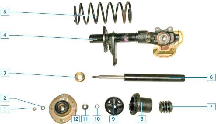
Shock absorber strut parts: 1 — shock absorber rod mounting nut; 2 - washer; 3 - rack housing nut; 4 — shock absorber strut housing with steering knuckle; 5 - spring; 6 — shock absorber; 7 — compression stroke buffer; 8 — case; 9 - upper support cup; 10 - flat washer; 11 - disc washer; 12 - upper support
The stand is made as a single unit with the steering knuckle.
The spring support cup and the pivot arm, which is connected to the steering rod via a ball end, are welded to the middle part of the strut body.
The telescopic strut is equipped with a helical cylindrical spring with an upper coil of reduced diameter, a rubber compression buffer, and an upper strut support assembly with a bearing.
A telescopic hydraulic shock absorber is installed in the rack housing.
The upper support is secured with three self-locking nuts to the mudguard cup of the body.
Due to its elasticity, the support allows the rack to swing during suspension movements and dampens high-frequency vibrations of the suspension.
The bearing pressed into it allows the rack to turn together with the steered wheel.
Braking and traction forces during vehicle movement are perceived by suspension arms connected via ball joints to steering knuckles and, via silent blocks and cushions, to the body.
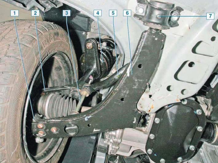
Elements of the front suspension on the car, bottom view: 1 - ball joint; 2 - steering knuckle; 3 — stabilizer strut; 4 — shock absorber strut; 5 — transverse stabilizer bar; 6 - lever; 7 — lever cushion mounting bracket
The lower part of the steering knuckle is connected to the front suspension arm via a ball joint.
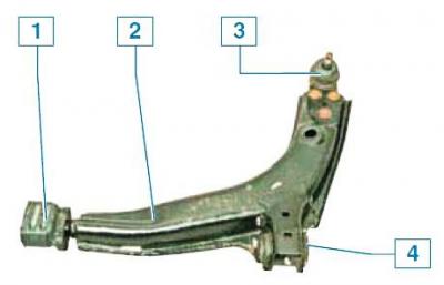
Front suspension arm: 1 - pillow; 2 - lever; 3 — ball joint; 4 — silent block
The ball joint pin is attached to the steering knuckle with a nut, and the support body is riveted to the lever with three rivets.
To replace the ball joint, you will need to drill out three rivets and replace them with bolts and nuts.
A double-row closed-type radial thrust ball bearing is pressed into the hole in the steering knuckle, and the wheel hub is pressed into the inner rings of the bearing.
The inner rings are tightened (through the hub) nut on the threaded part of the outer joint housing tailstock of the wheel drive.
During operation, the bearing is not adjusted and does not require replenishment of lubricant.
Wheel hub bearings are interchangeable.
The hub bearing nuts of both wheels are the same, with right-hand threads.
The anti-roll bar is made of spring steel.
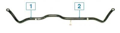
Transverse stabilizer bar: 1 - left side; 2 - right side
The bar in its middle part is attached to the front shield through rubber pads.
Both ends of the stabilizer bar are connected to the suspension arms via struts with rubber bushings.
The stabilizer bar has an asymmetrical shape.
To ensure good stability and control of the car, the front wheels are installed at certain angles relative to the body elements and suspension.
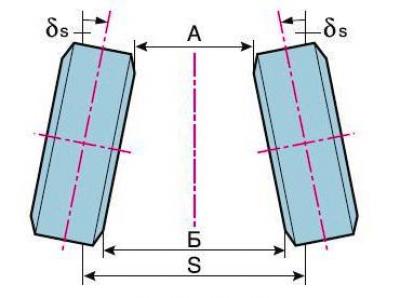
B–A — front wheel alignment; A and B — distance (mm) between the edges of the wheel rims in front and behind; δs — front wheel toe angle; S — track
Only the wheel alignment angle is adjustable.
Other parameters (camber angle, longitudinal tilt angle of the steering axis) are designed by the manufacturer and are not subject to adjustment.
Wheel toe is the angle between the plane of rotation of the wheel and the longitudinal axis of the vehicle.
Wheel alignment helps ensure the correct position of the steering wheels at different speeds and turning angles of the vehicle.
Signs of wheel alignment deviation from the norm: severe saw-tooth wear of tires in the transverse direction, squealing tires when turning, increased fuel consumption due to high rolling resistance of the front wheels.
The toe-in is adjusted by turning the adjusting screw with the terminal connections of the steering rod ends loosened.
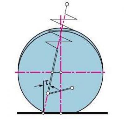
T — longitudinal inclination angle of the wheel rotation axis
The longitudinal tilt angle of the steering axis is the angle between the vertical and the line passing through the centers of rotation of the ball joint and the bearing of the upper support of the shock absorber strut in a plane parallel to the longitudinal axis of the vehicle.
It helps to stabilize the steered wheels in the direction of straight-line movement.
Symptoms of deviation of the angle from the norm include the car pulling to the side while driving, different forces on the steering wheel when turning left and right, and one-sided wear of the tire tread.
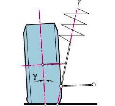
Y — camber angle
Wheel camber is the angle between the plane of rotation of the wheel and the vertical.
It helps to maintain the correct position of the rolling wheel when the suspension is operating.
If this angle deviates significantly from the norm, the vehicle may drift away from straight-line movement and the tread may wear on one side.
The camber angle of the wheels and the longitudinal tilt angle of the wheel pivot axis are determined by the design geometry of the suspension parts and are not subject to adjustment during operation.
It is recommended that the front wheel alignment angles and wheel alignment be checked at a service station.
Before adjustment, the wheels must be set to the position where the vehicle is moving straight ahead.
The vehicle must be placed on a horizontal platform and loaded in accordance with the manufacturer's recommendations.
With normal tire pressure and no excessive play in the front suspension assemblies, the installation angle values should correspond to the following values:
- – toe-in: 10'±10'
- – camber angle: –1°10'±20'
Angle of longitudinal inclination of the axis of rotation:
- – with power steering 2°45'±1°
- – without power steering 1°30'±1°
The original text can be found on the website CHEVYMAN