


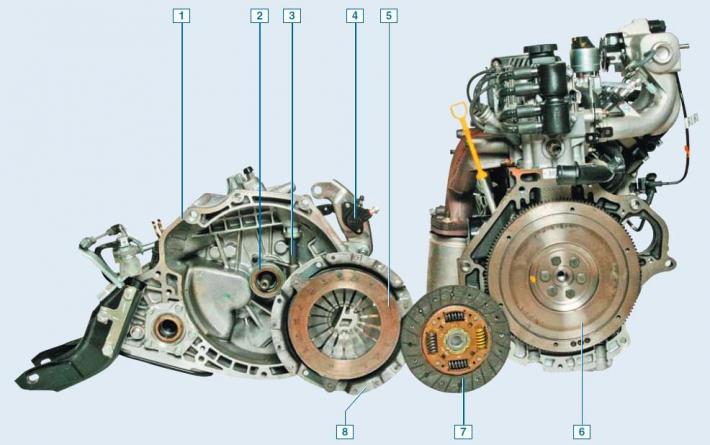
Clutch elements: 1 - gearbox housing; 2 — clutch release bearing; 3 — clutch release shaft; 4 — working cylinder; 5 - pressure plate; 6 — flywheel; 7 — slave disk; 8 — clutch housing (basket)
The clutch is single-disc, dry, with a central diaphragm-type spring.
It is located in an aluminum crankcase, structurally integrated with the gearbox and attached to the engine cylinder block.
The clutch housing is connected to the engine flywheel by six bolts.
The casing is connected to the pressure (leading) disk by three pairs of elastic steel plates.
This unit (it is also called the clutch "basket") is balanced as an assembly on a stand, so it is replaced entirely.
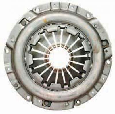
Clutch housing (basket)
A diaphragm spring is installed in the casing.
The "basket" needs to be replaced if the pressure spring petals are worn out in annular fashion, and if the ends of the petals are not located at the same level.
We also reject the "basket" if the force on the pedal decreases when disengaging the clutch, which indicates significant wear on the surface of the pressure plate or "settling" of the spring.
The driven disk with a spring-loaded torsional vibration damper is located on the splines of the primary shaft of the gearbox between the flywheel and the pressure plate.
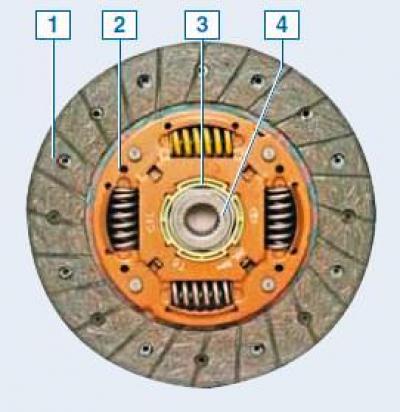
Clutch slave disc: 1 - friction linings; 2 — torsional vibration damper; 3 - idle damper; 4 — hub
The two friction linings of the disc are riveted on both sides to a spring plate, which in turn is riveted to one of the two damper plates.
The spring plate has a wavy shape.
When the clutch is engaged, the friction linings compress the spring plate, which helps to engage the clutch more smoothly.
A disc hub is installed between the damper plates.
The damper springs are installed in the grooves of the hub and damper plates.
The damper plates are connected by support pins.
In the disc hub opposite the support pins there are cutouts that allow the hub to rotate within certain limits relative to the damper plates, thereby compressing the damper springs.
This allows to reduce dynamic loads in the transmission when starting the car and when changing gears.
An idle damper is located on the driven disk hub in a plastic housing, which serves to dampen torsional vibrations and eliminate knocking in the gearbox when the engine is idling.
The driven disk is replaced if the axial runout of the linings is more than 0.5 mm, if there is oiling, cracking, scoring or uneven wear of the linings, if the riveted joints are loose, and also if the distance between the working surface of the lining and the rivet head is less than 0.2 mm.
The clutch release drive is hydraulic.
The force from the pedal to the clutch release fork is transmitted through the working fluid.
The clutch hydraulic drive reservoir is shared with the brake system hydraulic drive reservoir.
The clutch release shaft with a lever welded to it rotates on bushings installed in the clutch housing.
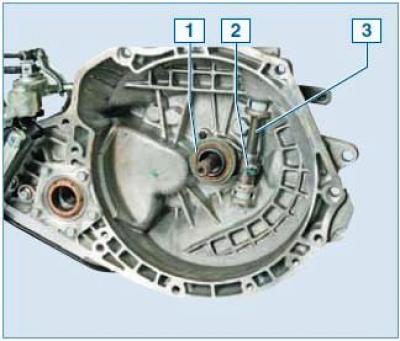
Elements of the clutch release drive mechanism: 1 — clutch release bearing; 2 — clutch release fork; 3 — clutch release shaft
The clutch release fork is secured to the shaft with a bolt.
A clutch release bearing is installed between the clutch release fork and the diaphragm spring petals.
The bearing moves freely along the guide sleeve, which is attached to the clutch housing with three bolts.
The spring in the working cylinder, through the pusher, lever and clutch release fork, constantly presses the bearing against the diaphragm spring of the casing.
The clutch pedal is mounted on the pedal assembly bracket axle.
The pedal is connected to the piston pusher of the clutch master cylinder.
The free travel of the clutch pedal is adjusted by rotating the pusher of the clutch master cylinder.
The clutch is disengaged as follows.
When the clutch pedal is pressed, pressure of the working fluid is created in the hydraulic system of the clutch release drive, as a result of which the piston of the working cylinder, moving together with the pusher, presses on the lever of the clutch release shaft, which rotates together with the clutch release fork and moves the bearing along the guide sleeve.
The bearing presses on the petals of the diaphragm spring.
The spring, being deformed, stops pressing the pressure plate against the flywheel, and the pressure plate moves away from the flywheel, as a result of which the engine crankshaft and the primary shaft of the gearbox can rotate independently of each other.
When the clutch pedal is released, the bearing returns to its original position, and the diaphragm spring again begins to press on the pressure plate, which, in turn, presses the driven disk against the flywheel - as a result, the transmission of torque is resumed.
The clutch release bearing contains a "lifetime" supply of grease and therefore does not require maintenance.
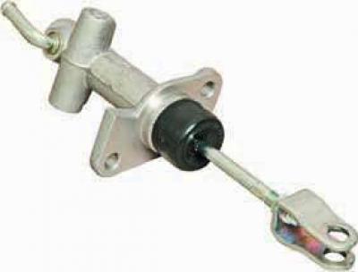
Clutch master cylinder
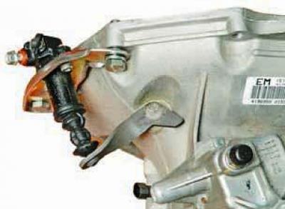
Clutch release slave cylinder