


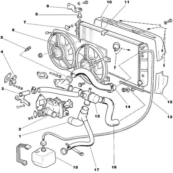
Figure 2-59. Engine cooling system:
1 - hose supplying to the pump;
2 - coolant pump;
3 - outlet pipe of the interior heater radiator;
4 - heater radiator supply pipe;
5 - coolant temperature sensor;
6 - electric fans of the cooling system;
7 - cork;
8 - radiator support;
9 - bracket;
10 - Upper radiator shroud;
11 - radiator;
12 - lower radiator casing;
13 - steam-air hose;
14 - radiator supply hose;
15 - thermostat;
16 - radiator drain hose;
17 - Filling hose;
18 - expansion tank.
The cooling system is liquid, closed type, with forced circulation of liquid, with expansion tank 18. Pump 2 (figure 2-59) the coolant is driven by a belt 7 (figure 2-60). Radiator 11 (figure 2-59) tubular-plate, aluminum, with plastic tanks. Casing 6 with two electric fans is attached to the radiator with five nuts. The electric fan has a plastic impeller mounted on the shaft of the electric motor, which is switched on and off by sensor 5.
The coolant is poured through the filler neck of the expansion tank 18. The expansion tank cap has an inlet and outlet valve.
[The article was reprinted from the website chevyman]