
- detach the housing 9 (figure 2-62) pump from cover 8;
- install universal puller 3 (figure 2-63) and press the fan pulley hub;
- remove lock screw 6 (figure 2-62), press out bearing 7 together with impeller 1 towards the oil seal;
- install a universal puller, press the impeller and remove the seal.
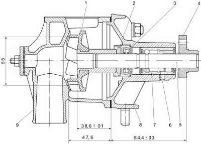
Figure 2-62. Longitudinal section of the coolant pump:
1 - impeller;
2 - thrust ring;
3 - oil seal;
4 - pulley hub;
5 - roller;
6 - bearing lock screw;
7 - bearing;
8 - lid;
9 - body.
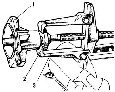
Figure 2-63. Removing the pulley hub:
1 - pump housing cover;
2 - pulley hub;
3 - universal puller.
Check. Check the axial clearance in the bearing. This operation must be performed if significant pump noise was noted. The clearance should not exceed 0.13 mm under a load of 49 N (5 kgf). If the clearance is greater, replace the bearing with a new one together with the shaft.
It is recommended to replace the pump seal and the gasket between the pump and the cylinder block with new ones during repairs.
Inspect the pump body and cover, no deformations or cracks are allowed.
Assembly. Assemble in the following order:
- press the seal into the housing cover using the 41.7853-4028 mandrel;
- press the new bearing with the roller into the cover, aligning the socket of the locking screw with the hole in the housing cover, tighten and seal the hole of the locking screw;
- press the fan pulley hub onto the shaft using a 25mm diameter, 20mm long process rod;
- using a mandrel (figure 2-64) press the impeller onto the roller; check the size 0.9-1.3 mm (figure 2-65);
- install the gasket and connect the cover to the body (socket wrench 13).
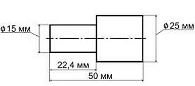
Figure 2-64. Mandrel sketch
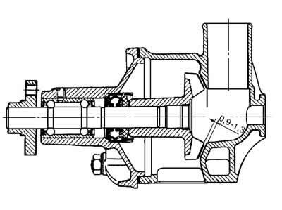
Figure 2-65. Assembled pump