
Note: Depending on the vehicle modification, the arrangement of fuses and relays in the mounting blocks may be different. The numbering order remains the same. A description of the circuits protected by the fuses can be found in the operating manual supplied with the vehicle.
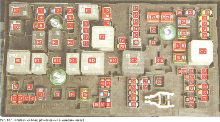
Table 10.1. Purpose of fuses, fuse links and relays in the mounting block located in the engine compartment
| Fuse/Relay Number | Current strength, A | Protected circuit |
| Fuses | ||
| 1 | 15 | Gearbox control unit |
| 2 | 15 | Engine control unit |
| 3 | - | Not used |
| 4 | 10 | Electromagnetic air valve of the adsorber |
| 5 | 15 | Ignition |
| 7 | - | Not used |
| 8 | 15 | Fuel injection system |
| 9 | 15 | Fuel injection system, ignition system |
| 10 | 15 | Engine control unit |
| 11 | 10 | Oxygen concentration sensor |
| 13 | 7,5 | Evaporative emission solenoid valve |
| 14 | Not used | |
| 15 | 20 | Rear window cleaner |
| 16 | 7,5 | Ignition, cabin air quality sensor |
| (air conditioning system) | ||
| 17 | 5 | Ignition, airbag |
| 18 | 10 | Throttle position sensor |
| 19 | - | Not used |
| 20 | 20 | Fuel pump |
| 22, 23,29 | - | Not used |
| 30 | 15 | ABS |
| 31 | 20 | Body equipment control unit |
| 32 | 20 | Same |
| 33 | 30 | Heated front seats |
| 34 | 25 | Roof hatch |
| 35 | 30 | Audio system |
| 36 | - | Not used |
| 37 | 10 | Right high beam headlight |
| 38 | 10 | Left high beam headlight |
| 39,40 | - | Not used |
| 46 | 10 | Cooling system fan |
| 47 | 10 | Oxygen concentration sensor |
| 48 | 15 | Fog lights |
| 49,50 | - | Not used |
| 51 | 15 | Sound signal |
| 52 | 15 | Dashboard |
| 53 | 10 | Electrochromic mirror |
| 54 | 5 | Light switch, |
| control of lighting devices | ||
| 55 | 7,5 | Folding mirrors |
| 56 | 15 | Windshield washer |
| 57 | 15 | Steering column lock |
| 58 | - | Not used |
| 60 | 7,5 | Mirror heater |
| 61 | 7,5 | Mirror heater |
| 62 | 10 | Air condition |
| 63 | 7,5 | Rear window sensor |
| 64 | 5 | Air quality sensor |
| 65 | 7,5 | Rear fog lights |
| 66 | 15 | Rear window washer |
| 67 | 20 | Fuel injection control unit |
| 68 | - | Not used |
| 69 | 5 | Battery voltage sensor |
| 70 | 5 | Rain sensor |
| 71 | - | Not used |
| Fusible links | ||
| 6 | 30 | Windscreen cleaner |
| 12 | 30 | Starter solenoid relay |
| 21 | 30 | Rear electric windows |
| 22 | - | Not used |
| 24 | 30 | Front electric windows |
| 25 | 20 | Electronically controlled vacuum pump |
| 26 | 40 | ABS |
| 27 | 30 | Electronic key management system |
| 28 | 40 | Rear window heating |
| 41 | - | Not used |
| 42 | 40/30/20 | Engine cooling fan |
| 43,44 | - | Not used |
| 45 | 40 | Engine cooling fan |
| 59 | 30 | Diesel Fuel Heater |
| Relay | ||
| R1 | Air conditioning compressor drive clutch | |
| R2 | - | Starter solenoid relay |
| R3 | - | Engine cooling fan (K7) |
| R4 | - | Front windshield wiper mode (speed) relay |
| R5 | - | Front windshield wipers |
| R6 | - | Not used |
| R7 | - | Smooth relay of the engine management system |
| R8 | Fuel pump | |
| R9 | - | Engine cooling system fan (K2) |
| R10 | - | Engine cooling system fan (K3) |
| R11 | - | Not used |
| R12 | - | Engine cooling system fan (K3) |
| R13 | - | Engine cooling system fan (K1) |
| R14 | - | Not used |
| R15 | - | Ignition |
| R16 | - | Pre-heating system (diesel) |
| R17 | - | Heated exterior rear view mirrors |
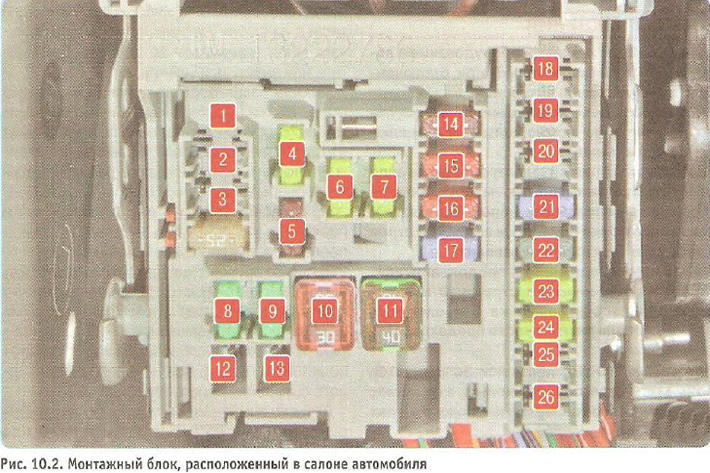
Table 10.2. Purpose of fuses and fusible links in the mounting block located in the vehicle interior
| Fuse/link number | Current strength, A | Protected circuit |
| Fuses | ||
| 1 | 10 | Infotainment system, hands-free telephone |
| 2 | - | Not used |
| 3 | 25 | Body equipment control unit |
| 4 | 20 | Infotainment system |
| 5 | 7,5 | Information display, parking assistance system |
| 6 | 20 | Cigarette lighter |
| 7 | 20 | Plug socket |
| 8 | 30 | Body equipment control unit |
| 9 | 30 | Body equipment control unit |
| 14 | 5 | Diagnostic connector |
| 15 | 10 | Airbag |
| 16 | 10 | Central locking, rear tailgate |
| 17 | 15 | Air conditioner |
| 18 | - | Not used |
| 19 | 5 | Gear shift lever |
| 20 | - | Not used |
| 21 | 15 | Devices |
| 22 | 2 | Ignition, electronic key control system |
| 23 | 20 | Body equipment control unit |
| 24 | 20 | Body equipment control unit |
| 25 | 20 | Steering column lock |
| 26 | - | Not used |
| Fusible links | ||
| 10 | 30 | Body equipment control unit |
| 11 | 40 | Electric fan for interior heating and air conditioning system |
| 12 | - | Not used |
| 13 | 25 | Heated seats |
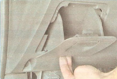
1. To access the fuse box located in the passenger compartment, open the small item storage box, pull the box up...
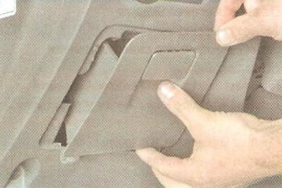
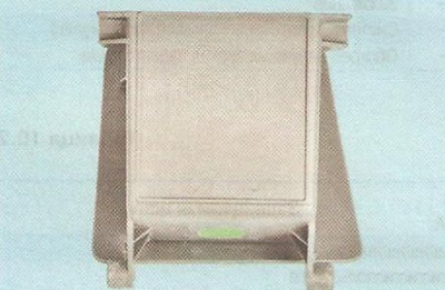
2. ...and remove the lower part of the glove box from the stops in the panel.
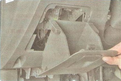
3. Remove the glove box to gain access to the fuse box located in the passenger compartment.
Note: The fuse box has a diagram of the fuse locations on the inside.
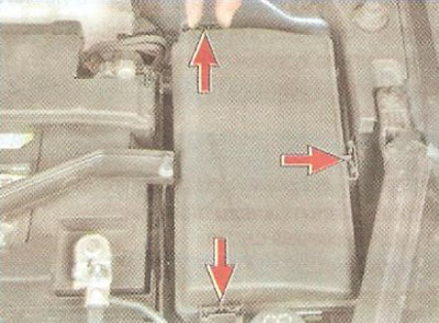
4. To gain access to the fuse box located in the engine compartment, press the three fasteners on the fuse box cover...
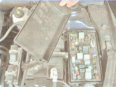
5. ...and remove the lid.
Note: The inside of the cover of the relay and fuse box located in the engine compartment contains a diagram of the location of the relays, fuses and fusible links.
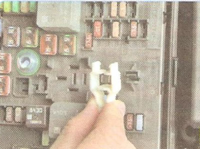
The mounting block is equipped with tweezers for removing fuses from mounting blocks.
6. Before replacing a blown fuse, find out the cause of the blown fuse and eliminate it. When searching for a fault, look at the circuits specified in Tables 10.1 and 10.2 that this fuse protects. If the new fuse blows again after a short time, the electrical equipment should be checked at a service center.
Fuse markings
| Color | Current strength, A |
| Light brown | 5 |
| Brown | 7,5 |
| Red | 10 |
| Blue | 15 |
| Yellow | 20 |
| White or transparent | 25 |
| Green | 30 |
| Orange | 40 |
Warning: Do not replace blown fuses with jumpers or fuses rated for a different amperage, as this may cause damage to electrical circuits and equipment, or even cause a fire.
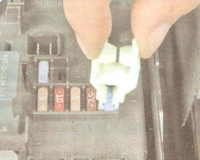
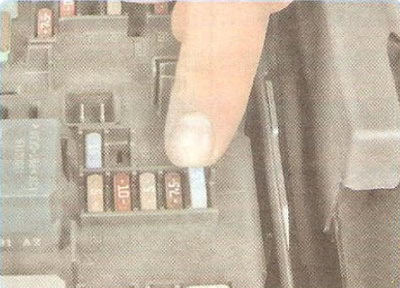
7. Use tweezers to grab the fuse...
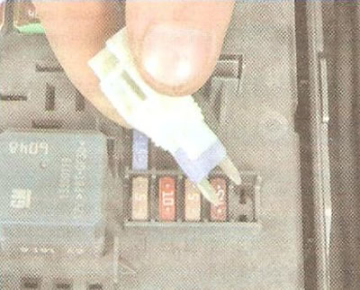
8. ...and pull it out of the connector.
9. Install a new fuse of the same rating as the one removed into the connector.
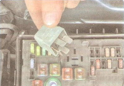
10. If replacement is necessary, remove the relay from the mounting block by rocking it from side to side and install a new one.
11. Replace fuse links in the same way as replacing relays.