


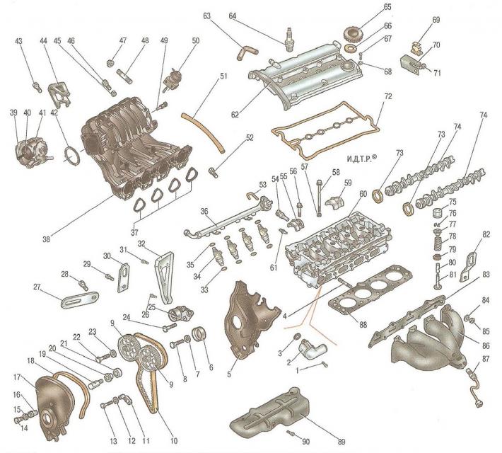
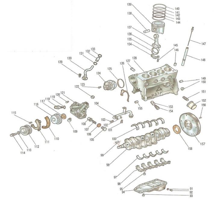
Fig. 5.1. Parts and assemblies of the F16D engine: 1, 8, 13, 14, 22, 24, 26, 28, 29, 31, 39, 43, 46, 52, 56, 58, 67, 71, 90, 93, 95, 101, 103, 104, 114, 115, 120, 123, 129, 145, 156 - bolts; 2 - thermostat; 3 - thermostat sealing ring; 4.48 - studs; 5 - rear cover of the timing belt; 6 - intermediate roller; 7, 12, 15, 23, 40, 45, 57, 68, 84, 113 - washers; 9 - camshaft toothed pulley; 10 - timing belt of the gas distribution mechanism; 11 - bracket; 16 - bushing; 17 - Front timing belt cover; 18 - lid sealing gasket; 19 - threaded stand; 20 - spacer sleeve; 21 - conical bushing; 25 - timing belt tensioner; 27 - generator adjustment bar; 30.82 - transport eyes; 32 - intake pipe mounting bracket; 33, 35 - injector sealing rings; 34 - nozzle; 36 - fuel rail; 37 - intake manifold gaskets; 38 - intake pipe; 41 - throttle assembly; 42 - throttle body gasket; 44 - Throttle cable housing mounting bracket; 47, 85 - nuts; 49 - intake air temperature sensor; 50 - vacuum drive of the intake manifold geometry change system; 51, 63 - crankcase ventilation hoses; 53 - Fuel pressure regulator vacuum hose; 54 - Engine Management System Coolant Temperature Sensor; 55 - Front camshaft bearing cover; 59 - middle camshaft bearing cap; 60 - cylinder head; 61 - Coolant temperature gauge sensor; 62 - cylinder head cover; 64 - spark plug; 65 - oil filler cap; 66 - plug sealing gasket; 69 - High voltage wire harness holder; 70 - holder bracket; 72 - cylinder head cover gasket; 73 - Front camshaft oil seal; 74 - camshaft; 75 - hydraulic valve drive clearance compensator; 76 - cracker; 77 - valve spring plate; 78 - valve spring; 79 - oil seal; 80 - valve guide bushing; 81 - valve; 83 - exhaust manifold sealing gasket; 86 - exhaust manifold; 87 - exhaust gas oxygen concentration sensor (lambda probe); 88 - Cylinder head gasket; 89 - exhaust manifold heat shield; 91 - Oil pan drain plug gasket; 92 - Oil pan drain plug; 94 - oil pan; 96 - main bearing caps; 97 - lower main bearing shells; 98 - crankshaft; 99 - key; 100 - upper main bearing shells; 102 - Oil receiver sealing ring; 104 - oil receiver; 105 - pressure reducing valve plug; 106 - sealing gasket of the pressure reducing valve plug; 107 - pressure reducing valve spring; 108 - plunger of the pressure reducing valve; 109 - safety valve; 110 - timing belt lower cover gasket; 111 - lower timing belt cover; 112 - crankshaft pulley; 116 - Crankshaft toothed pulley; 117 - Front crankshaft oil seal; 118 - Oil pressure warning light sensor; 119 - sensor sealing ring; 121 - oil pump; 122 - plug; 124 - water pump; 125 - Water pump sealing ring; 126 - Oil pump gasket; 127 - Cooling system pipe; 128 - cylinder block; 130 - crankcase ventilation system pipe; 131,133 - clamps; 132 - hose; 134 - connecting rod cover; 135 - lower connecting rod bearing shell; 136 - Upper connecting rod bearing shell; 137 - connecting rod; 138 - piston pin; 139 - piston; 140 - Upper compression ring; 141 - lower compression ring; 142 - Upper disc of oil scraper ring; 143 - Oil scraper ring expander; 144 - lower disc of oil scraper ring; 146, 149, 155 - mounting bushings; 147 - oil level indicator; 148 - pointer guide tube; 150 - cylinder block water jacket plug; 151 - Oil filter nipple; 152 - oil filter; 153 - bushing; 154 - bushing plug; 157 - flywheel; 158 - rear crankshaft oil seal
Cylinder head both engines are made of aluminum alloy with a transverse cylinder scavenging scheme (the inlet and outlet ports are located on opposite sides of the head), The valve seats and guide bushings are pressed into the cylinder heads. The intake and exhaust valves have one spring each, fixed through a plate with two crackers. The camshafts directly affect the valves through hydraulic compensators, which simultaneously perform the function of tappets.
Cylinder block engines are a single casting that forms the cylinders, cooling jacket, upper part of the crankcase and five crankshaft supports, made in the form of crankcase partitions. The block is made of special high-strength cast iron with cylinders bored directly in the block body. The main bearing caps of both engines are machined together with the blocks and are not interchangeable. The cylinder blocks have special bosses, flanges and holes for fastening parts, units and assemblies, as well as channels for the main oil line.
Crankshaft, forged from special steel, rotates in main bearings with thin-walled steel liners with an antifriction layer of aluminum-tin alloy. The axial movement of the crankshaft is limited by special flanges made on the middle main journal and resting on the flanges of the thicker liners of the middle main bearing.
Pistons are made of aluminum alloy. On the cylindrical surface of the piston head there are ring grooves for two compression rings and one oil scraper ring, the latter consisting of three sections. The engine pistons are additionally cooled by oil supplied through an opening in the upper head of the connecting rod and splashed onto the piston bottom.
Piston pins they are installed in the piston bosses with a gap and are pressed with tension into the upper heads of the connecting rods, which are connected with their lower heads to the connecting rod journals of the crankshaft through thin-walled liners, similar in design to the main ones.
Connecting rods steel, forged, with an I-section rod.
Lubrication system combined.
Crankcase ventilation system closed type does not communicate directly with the atmosphere, therefore, simultaneously with the suction of gases and gasoline vapors, a vacuum is formed in the crankcase in all engine operating modes, which increases the reliability of various engine seals and reduces the emission of toxic substances into the atmosphere. The ventilation system includes valve 3 (Fig. 5.2), ventilation hose 2, intake pipe 1 and a hose connecting the ventilation system to the diffuser of the throttle assembly.
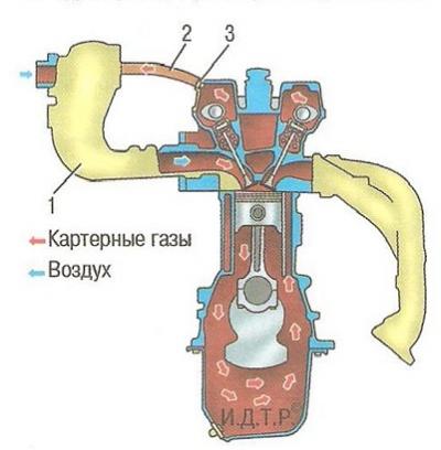
Fig. 5.2. Diagram of the engine crankcase ventilation system: 1 - inlet manifold; 2 - ventilation hose; 3 - ventilation system valve
Under the action of the vacuum in the intake manifold 1, crankcase gases are sucked through a channel in the engine cylinder block into the cavity under the valve timing cover, from where they enter the intake manifold 1 through valve 3 and ventilation hose 2, where they mix with the air supplied to the engine. The resulting gas mixture enters the engine cylinders together with the fuel and burns.
In some cases (for example, in case of severe wear of the cylinder-piston group or prolonged operation of the engine under high load) the ventilation system's capacity is insufficient. In this case, part of the crankcase gases is diverted to the throttle assembly, from where they are fed to the engine cylinders for combustion.
The main element of the system is valve 3. When the throttle valve is fully open, when the vacuum in the intake manifold is small, the valve is fully open under the action of the spring built into it and crankcase gases freely pass into the intake manifold. When the throttle valve is closed, (idle mode) the vacuum in the intake manifold increases, the valve cross-section decreases, the flow of crankcase gases into the manifold is limited and stable engine operation in idle mode is ensured.
Cooling system engines, hermetically sealed, with an expansion tank, consists of a cooling jacket made in casting and surrounding the cylinders in the block, combustion chambers and gas channels in the cylinder head. Forced circulation of the coolant is provided by a centrifugal water pump driven by a crankshaft toothed timing belt. To maintain the normal operating temperature of the coolant, a thermostat is installed in the cooling system, blocking a large circle of the system when the engine is not warmed up and the coolant temperature is low.
Power supply system both engines consist of an electric fuel pump in one module with a fuel filter installed in the fuel tank; throttle assembly, fuel pressure regulator, injectors and fuel lines, and also includes an air filter.
Helpful tips: With a certain amount of skill and attentiveness, many engine and system malfunctions can be determined quite accurately by the color of the smoke coming out of the exhaust pipe. Blue smoke indicates that oil is getting into the combustion chambers, and constant smoking is a sign of severe wear of the cylinder-piston group parts. The appearance of smoke during revving, after prolonged cranking by the starter, after long idling or immediately after engine braking usually indicates wear of the valve stem seals. Black smoke is a sign of an excessively rich mixture due to a malfunction of the engine management system or injectors. Gray or thick white smoke with an admixture of moisture (especially after the engine overheats) means that the coolant has entered the combustion chamber through a damaged cylinder head gasket. If this gasket is severely damaged, the liquid sometimes enters the oil pan, causing the oil level to rise sharply and the oil itself to turn into a cloudy whitish emulsion. White smoke (steam) from an unheated engine in damp or cold weather is normal.
Quite often you can see a car standing in the middle of a city traffic jam with the hood open, emitting clouds of steam. Overheating. Of course, it is better not to allow this, looking at the temperature gauge more often. But no one is insured against the fact that the thermostat, electric fan may suddenly fail, or the coolant may simply leak. If you missed the moment of overheating, do not panic and do not aggravate the situation. Overheating is not as scary as its possible consequences. Never turn off the engine immediately - it will get a heat stroke and, perhaps, after cooling down, will refuse to start at all. After stopping, let it run at idle speed, while the circulation of liquid in the system will remain. Turn on the heater at maximum power and open the hood. If possible, pour cold water on the radiator. Only after achieving a decrease in temperature, stop the engine. But never immediately open the cap of the expansion tank: on an overheated engine, a geyser from under the open cap is guaranteed. Take your time, let everything cool down, and you will preserve the health of the car and your own health. Almost all car manuals recommend that you always depress the clutch when starting the engine. This recommendation is justified only in the case of starting in severe frost, so as not to waste battery energy on turning the shafts and gears of the gearbox in thickened oil. In other cases, this is simply a recommendation so that the car does not move if a gear is engaged due to forgetfulness. This technique is harmful to the engine, since when the clutch is depressed, significant force is transmitted through it to the crankshaft thrust bearing, and when starting (especially cold) lubrication does not reach it for a long time. The bearing wears out quickly, the crankshaft gets axial play, and starting from a standstill begins to be accompanied by strong vibration. In order not to damage the engine, get into the habit of checking the position of the gearshift lever before starting and starting the engine with the handbrake tightened, without squeezing the clutch unless absolutely necessary.