


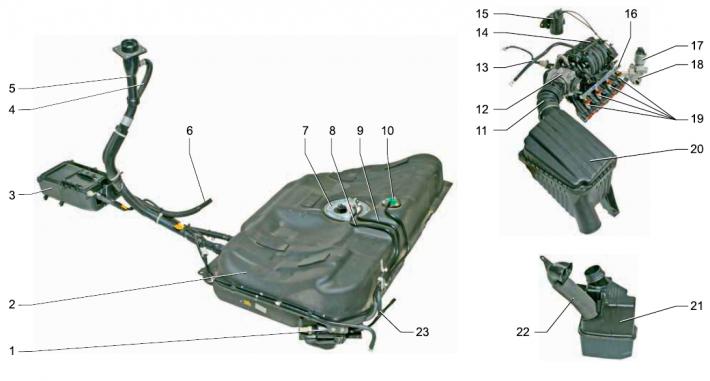
Elements of the engine power supply system: 1 - fuel filter; 2 - fuel tank; 3 — adsorber; 4 - ventilation tube; 5 - filling pipe; 6 — air supply pipe to the adsorber; 7 — fuel module; 8 — discharge line tube; 9 — drain line tube; 10 - gravity valve; 11 - corrugated air supply hose to the throttle assembly; 12 — throttle assembly; 13 — purge valve of the adsorber; 14 — intake manifold; 15 — vacuum reservoir assembly with valve of the intake tract length variation system; 16 — fuel rail; 17 — exhaust gas recirculation valve; 18 — recirculation valve spacer; 19 — injectors; 20 - air filter; 21 - resonator; 22 — air intake; 23 - tee
Fuel is supplied from a tank installed under the bottom near the rear seat. The fuel tank consists of two steel stamped parts welded together. The filler neck is connected to the tank by a plastic petrol-resistant tube, secured to the tank branch pipe with a clamp. Valves are installed in the filler neck plug, preventing deformation of the tank when the pressure inside it changes. The upper parts of the filler pipe and the fuel tank are connected by a plastic ventilation tube, which serves to remove air displaced from the tank during refueling.
The fuel module is installed in the tank, which includes a fuel pump, a fuel pressure regulator, a fuel level indicator sensor and a fuel reserve indicator lamp resistor.
To access the fuel module, there is a hatch under the rear seat cushion in the bottom of the car, covered with a lid.
The fuel gauge sensor sends signals to the gauge located in the instrument cluster.
The fuel pump is located inside the fuel module housing.
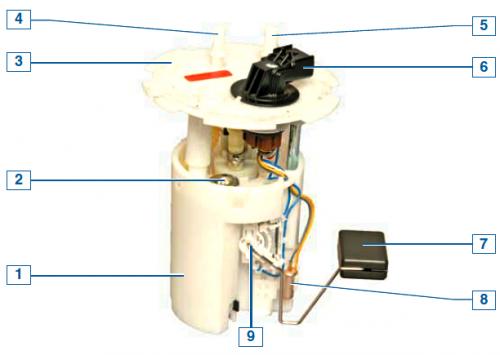
Fuel module: 1 — module body; 2 — fuel pressure regulator; 3 — module cover; 4 — drain line nipple; 5 — discharge line nipple; 6 - electrical connector; 7 — fuel level indicator sensor float; 8 — fuel reserve indicator lamp resistor; 9 — fuel level indicator sensor
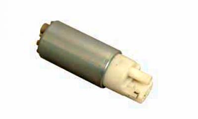
Fuel pump
The fuel pump is a non-separable unit and must be replaced if it fails. A mesh filter is installed at the pump inlet.
Pump capacity is not less than 60 l/h.
From the pump, fuel is supplied under pressure to the fuel filter
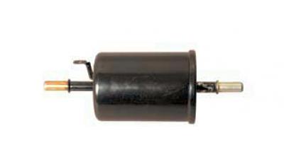
Fuel filter
Fine fuel filter — non-separable, in a metal housing, with a paper filter element. The filter is fixed to the fuel tank at the front on the right. After the filter, the fuel is supplied to the tee and through it to the fuel rail and the fuel pressure regulator located in the fuel module.
The fuel pump creates excess pressure in the system, exceeding the operating pressure of the fuel injectors.
The fuel pressure regulator ensures that excess fuel is discharged through the drain line into the fuel tank.
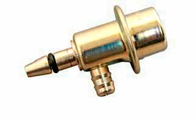
Fuel pressure regulator
The fuel pressure regulator is non-disassemblable and must be replaced if it fails. During engine operation, the regulator maintains the pressure in the discharge line within 2.8–3.3 bar.
The fuel rail is a metal tube with injectors installed on it.
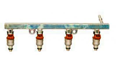
Fuel rail assembly with injectors
The ramp is attached to the intake manifold with two bolts.
The injector is fixed to the ramp with a metal locking bracket and sealed in the ramp and inlet pipe with rubber rings.
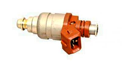
Nozzle
At the outlet of the injector there is a sprayer with two nozzles through which fuel is injected into the inlet channel of the pipeline.
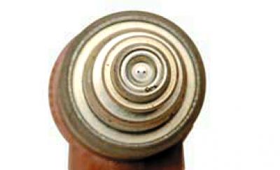
Nozzle sprayer
Controls the operation of the ECU injectors (electronic control unit). If there is a break or short circuit in the injector winding, the latter should be replaced. If the injectors are clogged, they can be washed without dismantling on a special service station stand.
Air enters the engine through the air intake, resonator, air filter, corrugated rubber hose, throttle body and intake manifold.
An air filter with a replaceable paper element ensures that the intake air is cleaned, and a resonator dampens the air intake noise. The air intake and resonator are located under the right front fender, and the air filter is located in the front part of the engine compartment on the right.
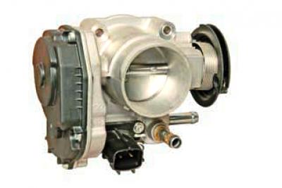
Throttle assembly
The throttle assembly is attached to the intake manifold and is a throttle body on which the idle speed control unit and throttle position sensor are installed. To prevent the throttle assembly from freezing at low temperatures and high humidity of the surrounding air, a heating unit is built into the assembly, through which the cooling system fluid circulates. When the gas pedal is pressed, the throttle valve opens, changing the amount of air entering the engine (fuel supply is calculated by the ECU depending on air consumption). When the engine is idling (throttle valve closed) The ECU controls the air supply using an idle speed controller, which is combined with the throttle position sensor into one unit.
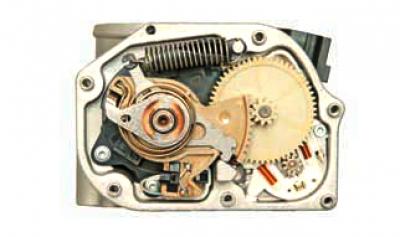
Idle speed control valve
For all engine operating modes, the ECU is programmed (calibration) required idle speed, which depends on the coolant temperature, vehicle speed, battery voltage and the state of the air conditioning system.
The regulator consists of an electric motor and a gearbox that transmits rotation from the electric motor shaft to the throttle shaft. The throttle opening angle at idle speed is 0–24°. If the idle speed regulator fails, the entire throttle assembly must be replaced.
After passing the throttle assembly, the air enters the intake manifold. From the common cavity of the intake manifold—the receiver—the air is supplied to the intake channels of the cylinder head through four separate channels.
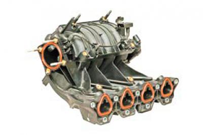
Inlet manifold receiver
To improve cylinder filling across the entire range of engine loads and speeds, a system for changing the length of the intake tract is used.
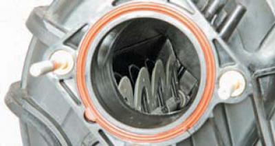
Location of the intake manifold length change system flaps in the intake manifold receiver
The design of the intake manifold allows changing the length of the air supply channels to the engine cylinders according to commands received from the ECU. For this purpose, four flaps are installed in the intake manifold receiver on a common shaft (one for each cylinder channel). When the shaft turns, the flaps open some channels and close others, directing air into the engine cylinders either along a short or a long path.
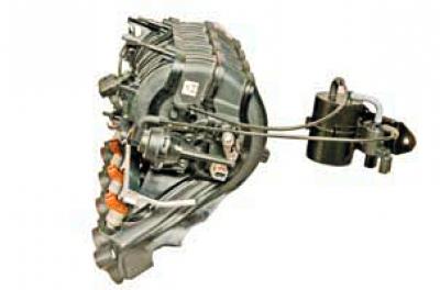
Elements of the intake tract length variation system
At low crankshaft speeds, the long intake tract provides high torque and good engine response; at higher revs, the short intake tract allows the engine to develop high power.
The shaft with the valves is turned by the actuator of the system, which consists of a pneumatic chamber, a vacuum tank, tubes and an electromagnetic valve.
The vacuum tank of the system is connected by a tube to the internal cavity of the receiver, and by a hose to the electromagnetic valve.
When the engine is running, the valve opens on command from the ECU, transmitting the vacuum from the reservoir to the pneumatic drive, which rotates the damper axis.
To reduce exhaust toxicity (by reducing the formation of nitrogen oxides) an exhaust gas recirculation system is provided. Its operating principle is to reduce the combustion temperature of the fresh fuel-air mixture in the engine cylinders by "diluting" it with exhaust gases taken from the exhaust manifold. The system consists of a recirculation valve secured via a spacer on the left end of the cylinder head, channels in the exhaust manifold and cylinder head, and a corrugated metal tube connecting the spacer to the intake manifold.
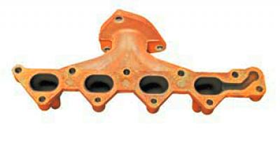
The exhaust gases are taken from the exhaust manifold through a channel made in the flange of the 4th cylinder pipe…
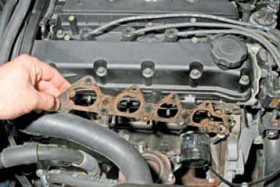
…and are fed through a channel in the cylinder head to the exhaust gas recirculation valve (through a spacer).
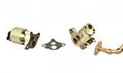
Exhaust gas recirculation system components: valve; metal gasket; spacer; corrugated tube
Depending on the engine operating mode, the recirculation valve regulates the amount of exhaust gases entering the intake manifold for combustion using signals from the electronic control unit.
The fuel system includes a fuel vapor recovery system, which includes an adsorber installed under the bottom of the car near the rear right wheel, and an electromagnetic valve for purging the adsorber, attached to the bracket of the intake manifold.
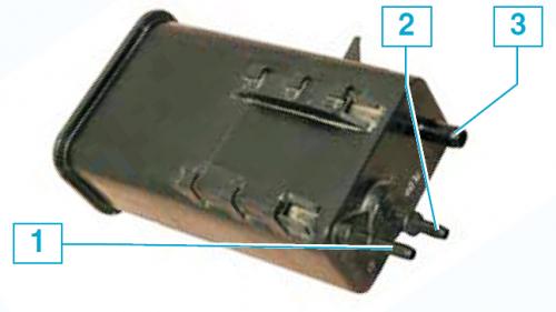
Adsorber: 1 — PURGE nipple of the fuel vapor discharge tube from the adsorber to the valve; 2 — TANK nipple of the fuel vapor supply pipe from the tank to the adsorber; 3 - AIR ventilation fitting
Fuel vapors from the tank enter the adsorber (container with activated carbon) through the fitting marked TANK, where it accumulates while the engine is not running. The second fitting of the adsorber marked PURGE is connected by a tube to the electromagnetic valve for purging the adsorber, and the third one marked AIR is connected to the atmosphere.
When the engine is stopped, the purge solenoid valve is closed, and in this case the adsorber does not communicate with the intake manifold.
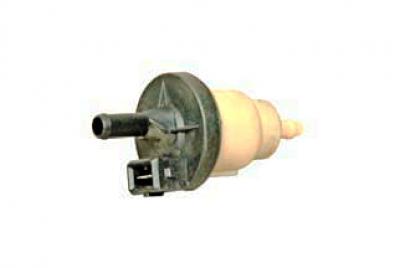
Evaporative Canister Purge Valve
When the engine is running, the electronic unit, by controlling the electromagnetic valve, purges the adsorber with fresh air due to the vacuum in the intake manifold.
Gasoline vapors are mixed with air and discharged into the intake manifold and then into the engine cylinders. The greater the air consumption of the engine, the longer the duration of the control pulses of the electronic unit and the more intense the purging.