


- fuel supply system, including the fuel tank, fuel module, fuel filter and fuel pressure regulator (is part of the fuel module), pipelines and fuel rail with injectors;
- air supply, which includes an air filter, air supply hose, throttle assembly;
- fuel vapor recovery system consisting of an adsorber, an adsorber purge valve and connecting pipelines.
Note: The fuel vapor recovery system is described in a separate subsection (see "Fuel vapor recovery system"), since it serves only to meet environmental requirements for reducing toxicity.
Functional purpose fuel supply systems - ensuring the supply of the required amount of fuel to the engine in all operating modes. The engine is equipped with an electronic control system with distributed fuel injection. In the distributed injection system, the functions of mixture formation and metering of the fuel-air mixture supply to the engine cylinders are separated: air is supplied by the air supply system, consisting of a throttle assembly, and the amount of fuel required at each moment of engine operation is injected by injectors into the intake pipe. This control method makes it possible to ensure the optimal composition of the combustible mixture at each specific moment of engine operation, which allows for maximum power with the lowest possible fuel consumption and low toxicity of exhaust gases. Controls the fuel injection system (as well as the ignition system) an electronic unit that continuously monitors the engine load, vehicle speed, engine thermal state, and the optimality of the combustion process in the engine cylinders using appropriate sensors.
The peculiarity of the injection system of the Chevrolet Cruze is the synchronous operation of the injectors in accordance with the valve timing (the engine control unit receives information from the phase sensor). The control unit switches on the injectors sequentially, and not in pairs, as in asynchronous injection systems. Each injector is switched on after 720° of crankshaft rotation. However, in starting modes and dynamic engine operation modes, an asynchronous fuel supply method is used without synchronization with crankshaft rotation.
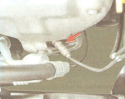
The main sensor for ensuring an optimal combustion process is oxygen concentration control sensor in exhaust gases (lambda probe). It is installed in the exhaust manifold of the exhaust system and, together with the engine control unit and injectors, forms a control circuit for the composition of the fuel-air mixture supplied to the engine. Based on the sensor signals, the engine control unit determines the amount of unburned oxygen in the exhaust gases and, accordingly, evaluates the optimality of the composition of the fuel-air mixture supplied to the engine cylinders at each moment in time. Having recorded a deviation of the composition from the optimal 1:14 (fuel/air), ensuring the most efficient operation of the catalytic converter of exhaust gases, the control unit changes the composition of the mixture using injectors. Since the oxygen concentration sensor is included in the feedback circuit of the engine control unit, the control circuit for the composition of the fuel-air mixture is closed.
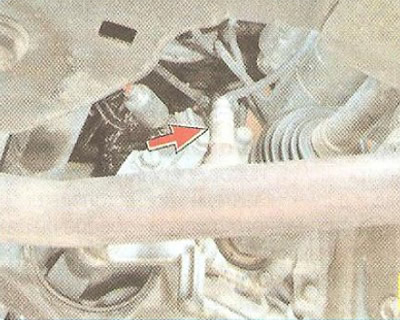
The peculiarity of the engine management system of the Chevrolet Cruze is the presence, in addition to the control sensor, of a second, diagnostic oxygen concentration sensor, installed in the exhaust pipe of the exhaust system. Based on the composition of the gases that have passed through the neutralizer, it determines the efficiency of the engine management system. If the engine control unit, based on information received from the diagnostic oxygen concentration sensor, records an excess of the exhaust gas toxicity standard that cannot be eliminated by calibrating the control system, it turns on the engine malfunction indicator lamp in the instrument cluster and stores the error code in memory for subsequent diagnostics.
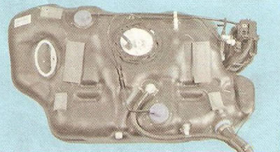
Fuel tank made of polymeric materials is installed under the bottom of the body in its rear part and attached to it with two clamps. In order to prevent fuel vapors from entering the atmosphere, the tank is connected to the adsorber by a pipeline. An electric fuel pump is installed in the flange opening in the upper part of the tank. From the pump, fuel is supplied to the engine fuel rail, fixed to the intake pipe. From the fuel rail, fuel is injected by injectors into the intake pipe.
Fuel lines power supply systems are tubes that connect various elements of the system together.
Warning: Fuel system hoses are made using a special technology from oil- and petrol-resistant materials. Using hoses that differ in design from those recommended may result in fuel system failure and, in some cases, fire.
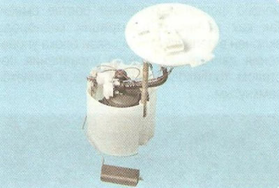
Fuel pump module includes an electric pump, fuel pressure regulator and fuel level indicator sensor.
The fuel pump module delivers fuel and is installed in the fuel tank, which reduces the likelihood of vapor lock, as the fuel is supplied under pressure, not under vacuum. Lubrication and cooling of the fuel pump components is also improved.
Submersible fuel pump, rotary type, with electric drive.
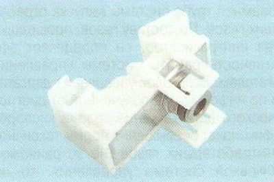
Fuel pressure regulator is installed in the fuel pump module and is designed to maintain constant fuel pressure in the fuel rail. The regulator is connected to the beginning of the supply line (immediately after the fuel filter) and is a relief valve with a spring that has a strictly calibrated force.
Fuel filter full-flow, structurally integrated with the fuel module housing. If the filter is clogged, the housing assembly must be replaced.
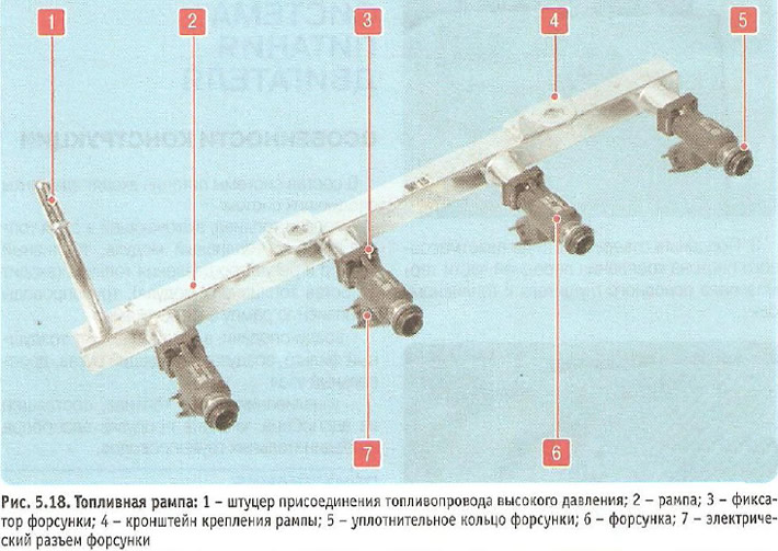
Fuel rail 2 (Fig. 5.18) is a hollow part with holes for the injectors, with a nipple 1 for connecting the high-pressure fuel line and brackets 4 for fastening to the inlet pipe. The injectors 6 are sealed in the ramp holes and in the inlet pipe sockets with rubber rings 5 and secured with spring clamps 3. The ramp assembly with the injectors is inserted with the injector tails into the inlet pipe holes and secured with two bolts.
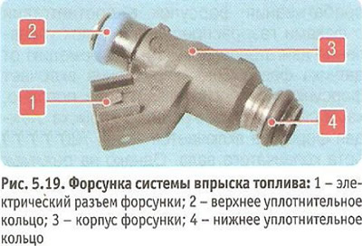
Nozzles (Fig. 5.19) are attached to the ramp from which fuel is supplied to them, and their nozzles enter the holes of the inlet pipe. In the holes of the ramp and the inlet pipe, the injectors are sealed with rings 2 and 4. The injector is designed for metered injection of fuel into the engine cylinder and is a high-precision electromechanical valve. Fuel under pressure comes from the ramp through channels inside the injector body to the shut-off valve. The spring presses the needle of the shut-off valve to the conical hole of the spray plate, holding the valve in the closed position. The voltage supplied from the engine control unit through electrical connector 1 to the winding of the injector electromagnet creates a magnetic field in it, drawing the core together with the needle of the shut-off valve into the electromagnet. The conical annular hole in the spray plate opens, and fuel is injected through the diffuser of the spray body into the intake channel of the cylinder head and further into the engine cylinder. After the electrical impulse stops, the spring returns the core and the needle of the shut-off valve to their original state - the valve is closed. The amount of fuel injected by the injector depends on the duration of the electrical impulse.
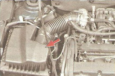
Air filter is installed in the right front part of the engine compartment on the car body. The lower branch pipe of the filter is inserted into the air duct of the intake noise muffler, installed under the right front wing.
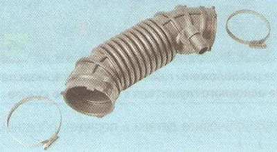
The filter is connected with a plastic corrugated air supply hose with throttle assembly.
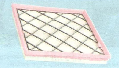
Air filter element paper, flat, with a large filtering surface area.
Throttle assembly (Fig. 5.20) is the simplest control device and is used to change the amount of main air supplied to the engine intake system. It is installed on the inlet flange of the intake pipe. A molded plastic sleeve is put on the inlet pipe of the throttle assembly, secured with a clamp and connecting the throttle assembly with the air filter.
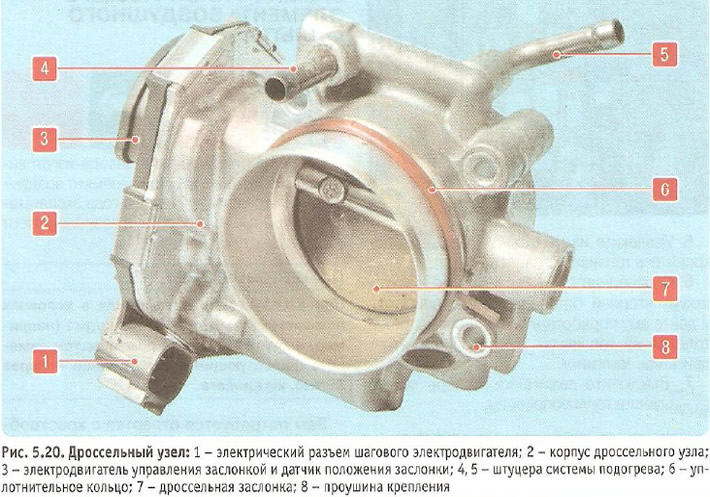
The throttle assembly includes a throttle position sensor and a stepper motor 3 for controlling the throttle valve. There is no mechanical connection between the throttle assembly and the throttle valve control pedal. The so-called "electronic" throttle valve control pedal transmits information about the degree of pressure on the pedal to the electronic engine control unit, which, in turn, taking into account the vehicle speed, the gear engaged, the engine load and the crankshaft speed, opens the throttle valve to the required angle.
The air filter does not have a seasonal adjustment device, so the throttle assembly is equipped with a heating system that prevents icing of the throttle valve in cold weather and is connected to the engine cooling system by hoses.
During operation, the throttle assembly does not require maintenance or adjustment; just monitor the condition of the rubber seals to avoid air leakage.
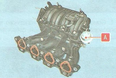
The intake pipe is equipped with variable intake tract length system, which allows for increased power to be developed at high engine crankshaft speeds (minimum intake tract length) and maximum torque in the low and mid-range speed range (increased intake tract length). The length of the intake pipe channels is changed by a signal from the engine control unit by turning the valve inside the intake pipe using a pneumatic chamber A, which is connected to the engine vacuum system via an electromagnetic valve.
(The article was reprinted from the website «chevyman.ru»)