


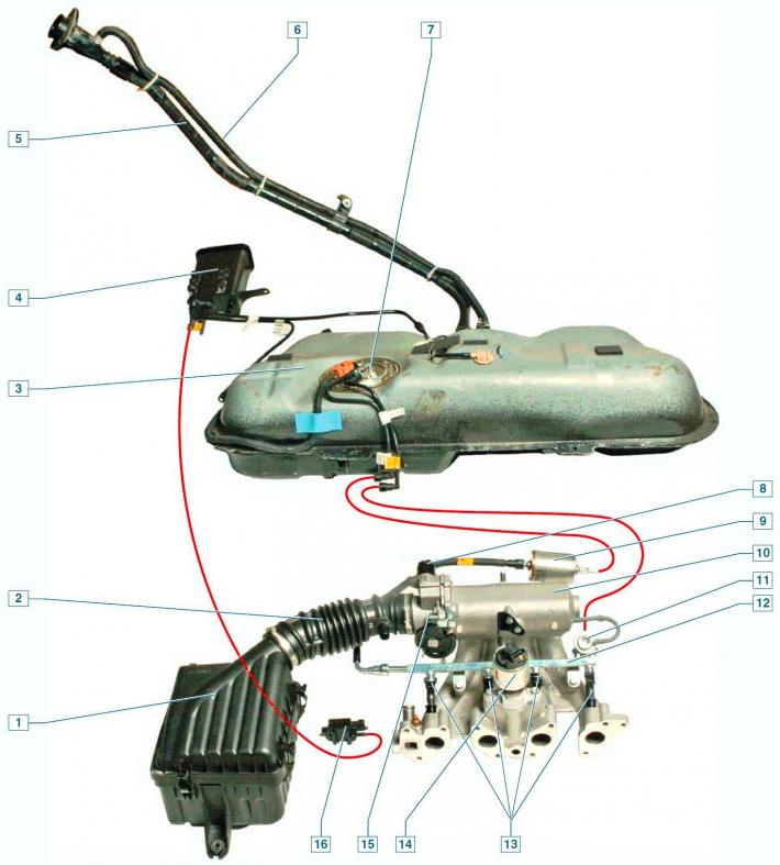
Elements of the engine power supply system: 1 - air filter; 2 - corrugated air supply hose to the throttle assembly; 3 - fuel tank; 4 — adsorber; 5 - filling pipe; 6 - ventilation tube; 7 — fuel module; 8 — idle speed controller; 9 — fuel filter; 10 — intake manifold; 11 — fuel pressure regulator; 12 — fuel rail; 13 — injectors; 14 — recirculation valve; 15 — throttle assembly; 16 — purge valve of the adsorber
Fuel is supplied from a tank installed under the bottom in the area of the rear seat.
The fuel tank consists of two stamped steel parts welded together.
The filler neck is connected to the tank by a plastic petrol-resistant filler pipe, secured to the tank nozzle with a clamp.
The filler cap is equipped with valves that prevent the tank from deforming when the pressure inside it changes.
The upper parts of the filler pipe and the fuel tank are connected by a plastic ventilation tube, which serves to remove air displaced from the tank during refueling.
The tank contains a fuel module, which includes a fuel pump and a fuel level indicator sensor with a fuel reserve indicator lamp resistor.
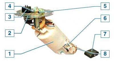
Fuel module: 1 — module body; 2 — module cover; 3 — Engine management system wiring harness connector; 4 — drain line nipple; 5 — discharge line nipple; 6 — fuel level indicator sensor; 7 — fuel level indicator sensor float; 8 — fuel reserve indicator lamp resistor
To access the fuel module, there is a hatch under the rear seat cushion in the bottom of the car, covered with a lid.
The fuel gauge sensor sends signals to the gauge located in the instrument cluster.
The fuel pump is located inside the fuel module housing.
It is very difficult to replace the pump separately, therefore, if it fails, it is advisable to replace the pump at an authorized service center or replace the fuel module as a whole.
From the pump, fuel is supplied under pressure to the fuel filter.
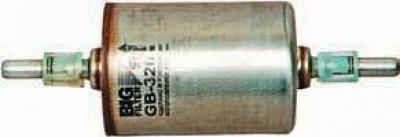
Fuel filter
Fine fuel filter - non-separable, in a metal housing, with a paper filter element.
The filter is fixed in the engine compartment on the front panel.
There is an arrow on the filter body that should match the direction of fuel flow.
After the filter, the fuel enters the fuel rail.
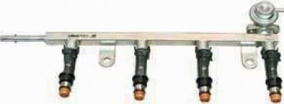
Fuel rail assembly with injectors and fuel pressure regulator
The fuel rail is a metal tube with injectors installed on it.
The ramp is attached to the intake manifold with two bolts.
The fuel pressure regulator is located on the left end of the ramp.
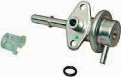
Fuel pressure regulator
The fuel pump creates excess pressure in the system, exceeding the operating pressure of the fuel injectors.
The pressure regulator ensures that excess fuel is discharged through the drain line into the fuel tank.
The pressure regulator is a fuel valve connected to a spring-loaded diaphragm.
Under the action of the spring, the valve is closed.
The diaphragm divides the regulator cavity into two isolated chambers – "fuel" and "air".
the "air" line is connected by a vacuum hose to the intake manifold, and the "fuel" line is connected directly to the ramp cavity.
When the engine is running, the vacuum, overcoming the resistance of the spring, tends to draw in the diaphragm, opening the valve.
On the other hand, fuel exerts pressure on the diaphragm, also compressing the spring.
As a result, the valve opens and some of the fuel is released through the drain line back into the tank.
When you press the gas pedal, the vacuum behind the throttle valve decreases, the diaphragm, under the action of the spring, closes the valve - the fuel pressure increases.
If the throttle valve is closed, the vacuum behind it is maximum, the diaphragm pulls the valve more strongly - the fuel pressure decreases.
The pressure regulator is non-separable and must be replaced if it fails.
The injector is fixed to the ramp with a metal locking bracket and is sealed in the ramp and intake manifold with rubber rings.
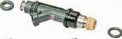
Nozzle with sealing rings
At the outlet of the injector there is a sprayer through which fuel is injected into the intake channel of the manifold.
The injectors are controlled by an electronic control unit.
If there is a break or short circuit in the injector winding, the latter should be replaced.
If the injectors become clogged, they can be washed without dismantling them on a special service station stand.
Air enters the engine through the air intake, resonator, air filter, corrugated rubber hose, throttle body and intake manifold.
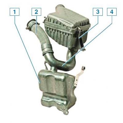
Elements of air supply to the throttle assembly: 1 - resonator; 2 — air intake; 3 - air filter; 4 - resonator tee
An air filter with a replaceable paper element ensures cleaning of the intake air, and a resonator dampens air noise at the intake.
The air intake and resonator are located under the right front fender, and the air filter is located at the front of the engine compartment on the right.
The throttle assembly is attached to the intake manifold and is the throttle body (with channels made in it), on which the idle speed controller and throttle position sensor are installed.
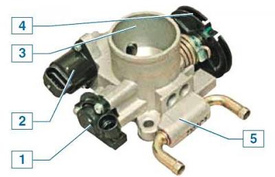
Throttle assembly: 1 - throttle position sensor; 2 - idle speed controller; 3 — body; 4 — damper drive sector; 5 — heating block
To prevent freezing of the throttle assembly at low temperatures and high humidity of the surrounding air, a heating unit is built into the assembly, through which the cooling system fluid circulates.
When you press the gas pedal, the throttle valve opens, changing the amount of air entering the engine (fuel supply is calculated by the control unit depending on the air flow).
When the engine is idling (throttle valve closed) The ECU controls the air supply using the idle speed control valve.
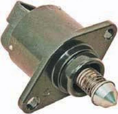
Idle speed control valve
The idle speed control valve is a stepper motor that moves the valve.
The valve shut-off element (needle) changes the flow area of the channel and ensures regulation of the air flow bypassing the throttle valve.
To increase the crankshaft speed at idle, the electronic unit sends a control signal to open the valve, increasing the air supply bypassing the throttle valve, and, conversely, to reduce the speed, a command is sent to close the valve.
In addition to controlling the idle speed of the crankshaft, the control unit, using the regulator, reduces the toxicity of exhaust gases - when the engine brakes, the throttle valve closes sharply, in this case the regulator increases the air supply bypassing the throttle valve, resulting in a leaner fuel mixture.
This helps reduce hydrocarbon and carbon monoxide emissions.
The idle speed regulator is non-separable and must be replaced if it fails.
After passing through the throttle assembly, the air enters the intake manifold.
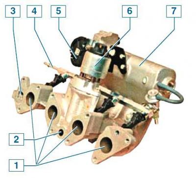
Intake manifold assembly: 1 — air supply channels to the cylinder head; 2 — exhaust gas supply channel from the cylinder head to the recirculation valve; 3 - coolant channel; 4 - fuel rail with injectors; 5 — throttle assembly; 6 — recirculation valve; 7 — receiver
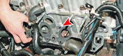
Exhaust gas sampling channel from the cylinder head (intake manifold removed)
From the common cavity of the intake manifold-receiver, air is supplied through four separate channels to the intake channels of the cylinder head.
In order to ensure that the engine cylinders are filled with air equally, the air supply channels are made approximately the same length.
To reduce exhaust toxicity (by reducing the formation of nitrogen oxides) an exhaust gas recirculation system is provided.
The principle of its operation is to reduce the combustion temperature of the fresh fuel-air mixture in the engine cylinders by diluting it with exhaust gases taken from the exhaust channel of the cylinder head.
The system consists of a recirculation valve attached to the intake manifold and passages in the intake manifold and cylinder head.
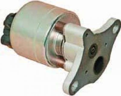
Recirculation valve
Depending on the engine operating mode, the valve regulates the amount of exhaust gases entering the intake manifold for combustion using signals from the electronic control unit.
The fuel system includes a fuel vapor recovery system, which includes an adsorber installed under the bottom of the car near the rear right wheel, and an electromagnetic valve for purging the adsorber, attached to the lower bracket of the generator.
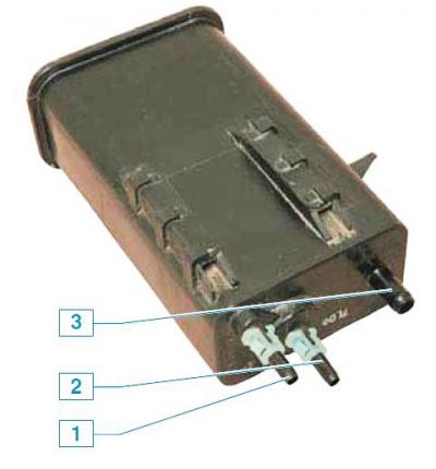
Adsorber: 1 — fuel vapor discharge pipe fitting from the adsorber to the electromagnetic valve; 2 — fuel vapor supply pipe fitting from the tank to the adsorber; 3 — air supply nipple
Fuel vapors from the tank enter the adsorber (container with activated carbon) through the fitting marked "TANK", where it accumulates while the engine is not running.
The second nipple of the adsorber with the inscription "PURGE" is connected by a tube to the electromagnetic valve of the adsorber purge, and the third with the inscription "AIR" - to the atmosphere.
When the engine is stopped, the purge solenoid valve is closed, and in this case the adsorber does not communicate with the intake manifold.
When the engine is running, the electronic unit, by controlling the electromagnetic valve, purges the adsorber with fresh air due to the vacuum in the intake manifold.
Gasoline vapors are mixed with air and discharged into the intake manifold and then into the engine cylinders.
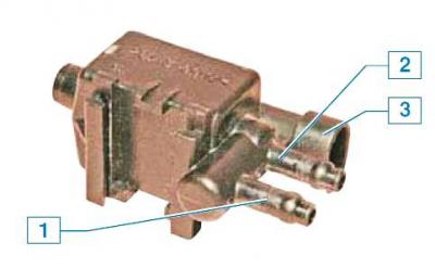
Evaporative Evaporative Canister Purge Solenoid Valve: 1 — nipple of the tube connecting the valve to the adsorber; 2 - a nipple of the tube connecting the valve to the intake manifold; 3 - electrical connector
(The original text can be found on the website ChevyMan)