


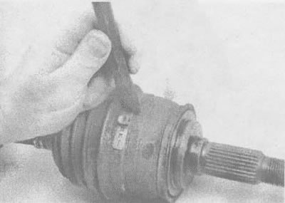
3.4a. Cut off the strip of fastening of the protective cover on the shaft, then move the protective cover to the center of the axle shaft |
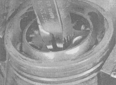
3.4b. Remove the thrust ring, move the hinge and remove the old protective cover |
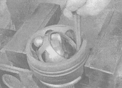
3.4v. Press on the outer raceway so that the balls can be removed; if it is difficult to tilt, gently tap the separator and inner raceway with a punch or hammer |
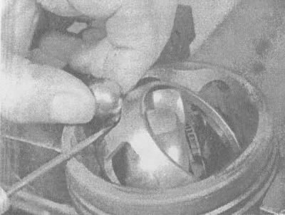
3.4g. Remove the balls from the separator one by one using a blunt screwdriver or a wooden block |
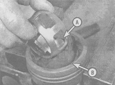
3.4d. Tilt the inner raceway and cage 90°, then align the holes in the cage (A) with the housing sections (B) and rotate the inner raceway up and down from the outer raceway |
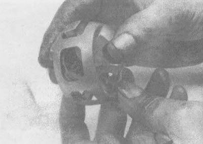
3.4e. Align the inner raceway sections with the cage raceway and turn the inner raceway out of the cage |
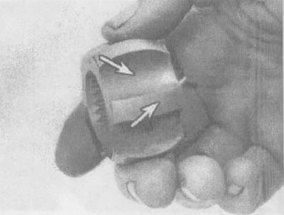
3.4g. After cleaning the parts with solvent, check the edges and grooves of the inner track for corrosion and traces of scratches, burrs and grooves |
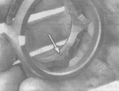
3.4z. Check the separator for cracks, corrosion, grooves, burrs and scratches (shiny spots are normal and do not have a negative effect on the operation of the joint) |
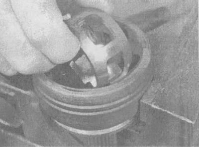
3.4i. Having placed the raceway and separator at an angle of 90°, lower the unit into the casing |
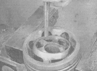
3.4k. Turn the hinge by gently tapping with a hammer and punch, then... |
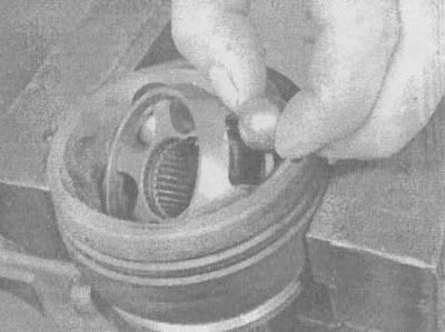
3.4L... insert the balls one by one into the separator windows until you have installed them all |
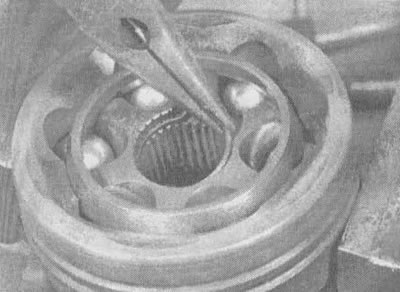
3.4m. Using pliers, lower the thrust ring into the groove, then... |
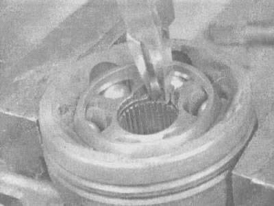
3.4n.... seat its ring in the groove using special pliers for thrust rings |
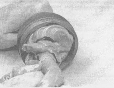
3.4o. Put grease into the constant velocity joint through the inner spline hole, then... |
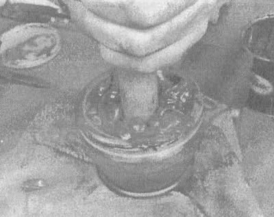
3.4p....insert a wooden rod (diameter slightly larger than the diameter of the axle shaft) through the spline hole and press down on it - this will force the grease into the joint. Repeat this operation until the entire bearing is completely surrounded by grease |
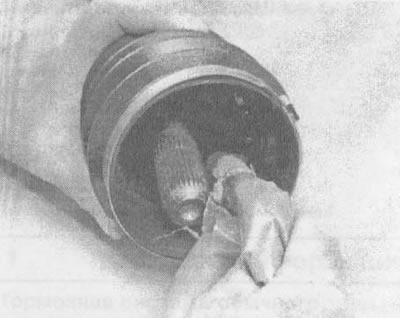
3.4p. Put the protective cover on the axle shaft and put grease inside the protective cover of the axle shaft until... |
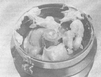
3.4 sec....until the lubricant level reaches the end of the axle shaft |
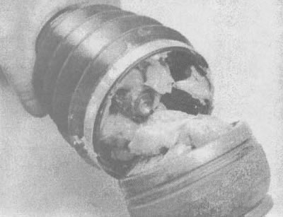
3.4t. Install the constant velocity joint on the axle shaft, aligning the splines; then, using a soft-faced hammer, push the joint onto the axle shaft until the thrust ring seats in the groove |
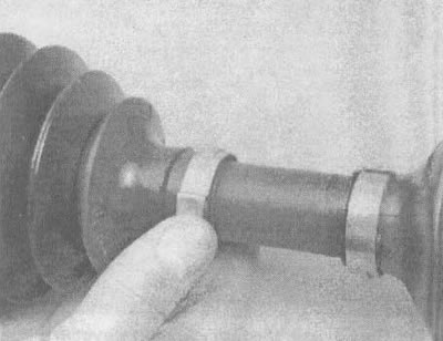
3.4u. Insert the inner end of the protective cover into the groove and put on the fixing clamp, then do the same on the other end of the protective cover; tighten the clamps of the protective cover using a special device (see illustration 3.3u)
The article is based on data from the website: «CHEVYMAN.RU»