


You will need: a flat-blade screwdriver, side cutters, a punch, a hammer, and a snap ring puller.
1. Remove the front wheel drive assembly (see "Removal and installation front wheel drives").
2. Clean the parts and inspect the drive:
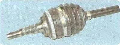
- the outer constant velocity joint should rotate with light force without jerking or jamming, radial and axial play. If any, replace the joint;
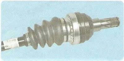
- the inner hinge should move in angular and axial directions with slight force, while jerking, jamming and radial play should not be felt. Otherwise, replace the inner hinge;
- the outer and inner hinge protective covers should not have any cracks or tears. Replace damaged covers;
- the wheel drive shaft must not be deformed. Replace the deformed shaft.
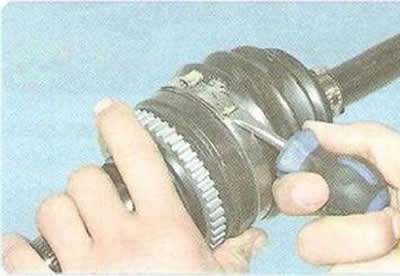
3. To replace the outer hinge or its cover, use a screwdriver to separate...
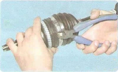
4. ...or have a bite with side cutters...
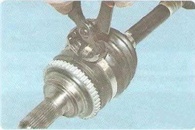
5. ...or use pliers to lock the clamp securing the large outer hinge cover and remove the clamp.
Note: The clamps for fastening the CV joint protective boots are single-use, replace them with new ones during assembly. As a rule, the clamps are included with the new joint.
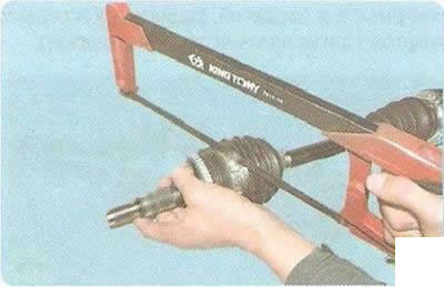
To make removal easier, the clamp can be cut with a hacksaw for metal. When cutting the clamp, be careful not to damage the edges of the groove for the cover on the hinge body.
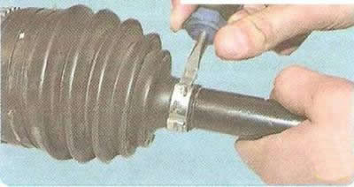
6. Remove the second cover mounting clamp in the same way.
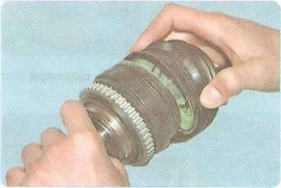
7. Slide the protective cover off the hinge housing...
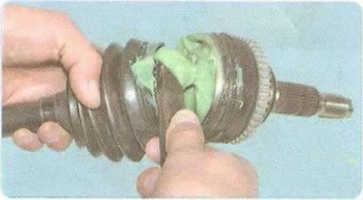
8. ...and remove some of the grease from it to expose the retaining ring.
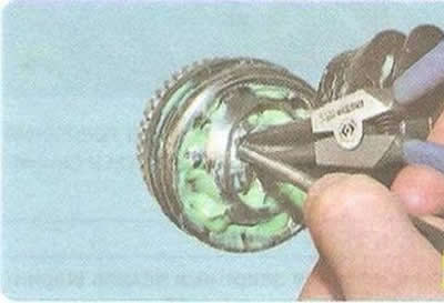
9. Spread the retaining ring tabs, while simultaneously moving the joint sleeve along the shaft splines with a punch...
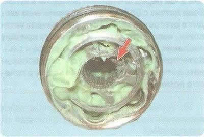
This is how the retaining ring is located in the hinge cage (for clarity, shown on a removed hinge).
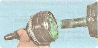
10. ...and remove the outer joint from the shaft.
Warning: Disassembly of the outer joint is not permitted.
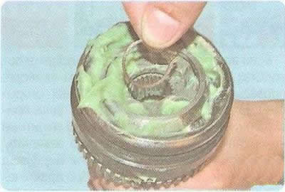
11. Remove the retaining ring from the groove in the cage.
When assembling, replace the retaining ring with a new one. As a rule, the ring is included with the new joint.
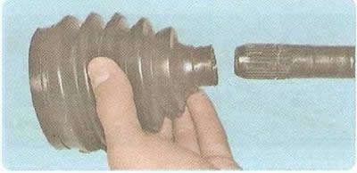
12. Remove the protective cover from the drive shaft.
Note: When installing the hinge, replace the protective cover with a new one. The cover is usually included with the new hinge.
Helpful Hints: To avoid damaging the hinge boot during assembly, wrap the splined portion of the shaft with insulating tape.
To facilitate installation of the boot on the shaft, lubricate the shaft with a thin layer of grease designed to fill the joint.
13. Before installing the new outer joint, fill its cavity with grease (if the joint was not lubricated by the manufacturer) in the amount of about 100 g. First, fill the hinge body, and then evenly distribute the remaining amount in the corrugations of the cover.
Warning: Do not reduce or increase the recommended amount of grease in the joint.
14. Install the outer joint boot and the joint in the reverse order of removal. When installing the joint on the shaft, press the joint by hitting the joint shank with a hammer through a soft metal punch until the joint collar is secured with a retaining ring.
Warning: Before securing the hinge boot with a large clamp, pull the edge of the boot with a screwdriver to equalize the air pressure inside and outside the boot. If excess air is not removed from under the boot, the boot may be damaged during operation.
There are some rules when "crimping" clamps.
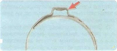
This is what a new, "uncrimped" clamp looks like.
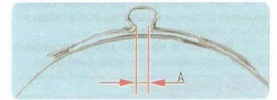
The criterion for the correct "compression" of the clamp is the gap A. It should be within 2.4-2.8 mm. If the gap is larger, "press" the clamp to the norm; if less, replace the clamp.
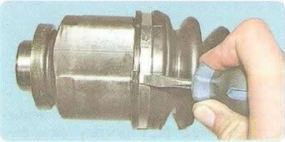
15. To disassemble and replace the inner Tripod type hinge, remove the clamps securing the hinge boot to its body...
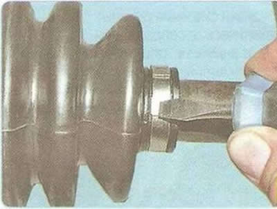
16. ...and to the shaft in the same way as was done for the outer hinge and the inner hinge of the Lebro type (see above in this subsection).
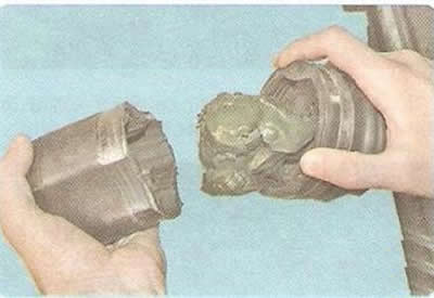
17. Disconnect the inner joint housing from the drive.
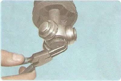
18. Use a puller to loosen the hub retaining ring...
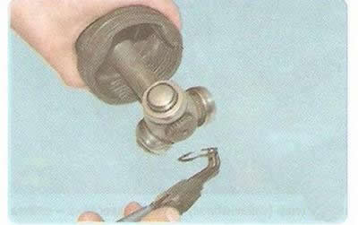
19. ...and remove the ring by removing it from the shaft groove.
Note: Grease has been removed from the joint for clarity.
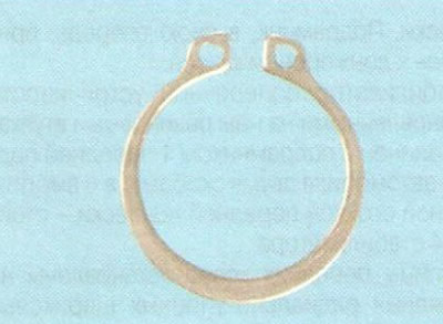
When assembling, replace the retaining ring with a new one. As a rule, the ring is included with the new joint. Make sure that the ring is completely inserted into the groove of the shaft.
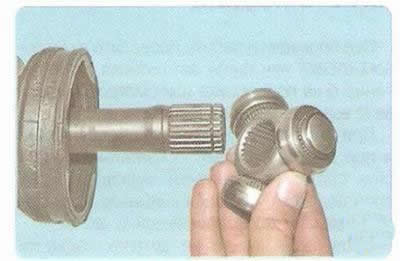
20. Remove the hub with rollers from the shaft splines...
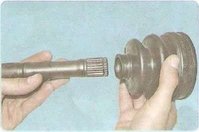
21. ...and remove the protective cover from the shaft.
Note: When installing the hinge, replace the protective cover with a new one. The cover is usually included with the new hinge.
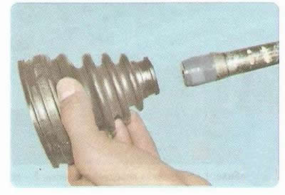
To avoid damaging the joint cover during assembly, wrap the splined part of the shaft with insulating tape.
To facilitate installation of the boot on the shaft, lubricate the shaft with a thin layer of grease designed to fill the joint.
22. Wash all metal parts with kerosene until all old grease is removed.
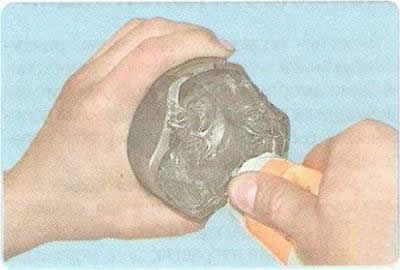
23. Before assembly, fill the housing cavity and the inner hinge cover with approximately 150 g of grease: 100 g in the hinge, 50 g in the cover.
Warning: Do not reduce or increase the recommended amount of grease in the joint.
24. Assemble the inner Tripod joint in the reverse order of disassembly.
Warning: Before securing the hinge boot with a large clamp, pull the edge of the boot with a screwdriver to equalize the air pressure inside and outside the boot. If excess air is not removed from under the boot, the boot may be damaged during operation.
There are some rules when "crimping" clamps.
The criterion for the correct "compression" of the clamp is the gap A. It should be within 2.4-2.8 mm. If the gap is larger, "press" the clamp to the norm; if less, replace the clamp.
(The original text can be found on the website «CHEVYMAN.RU»)