
ChevyMan.ru
Mazda Mitsubishi Toyota Land Rover Honda Kia Nissan
English Русский
Български
Беларускі
Український
Српски
Hrvatski
Română
Polski
Slovenský
Magyar
|
Articles | Sitemap | Contacts |


Home   Aveo   Captiva   Cruze   Lacetti   Lanos   Niva   Tahoe   Others  
Orlando 1 (2010-2018) Trailblazer 1 (2001-2008, petrol) Lumina 1 (1989-1994)
  • Home
  • Chevrolet
  • Lumina 1
  • Transmission
  • Drive shafts
  • Removal and installation axle shafts

Removal and installation axle shafts (Chevrolet Lumina 1)

            0

Contents: Removal ↧ Installation ↧

Removal


1. Loosen the wheel nuts, raise the front of the vehicle and securely support it on struts. Set the vehicle's parking brake and block the rear wheels to prevent the vehicle from rolling off the stands. Remove the front wheel.

2. Unscrew the drive axle hub nut. To prevent the hub from turning, insert a screwdriver through the caliper into the disc ventilation hole, then unscrew the nut (see illustration).
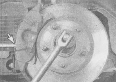
2.2. A screwdriver inserted through the caliper into the disc ventilation hole will hold the hub…

2.2. A screwdriver inserted through the caliper into the disc ventilation hole will hold the hub stationary when the hub nut is loosened


3. Remove the brake caliper (do not disconnect the brake hose) and the disk and tie the support to the side on the wire (see chapter 9, sections 3 and 4).

4. Separate the steering arm from the steering knuckle (see chapter 10, section 5).

5. Remove the axle shaft from the hub, then tie the outer end of the axle shaft with wire to prevent damage to the inner constant velocity joint (see illustration). If the axle shaft is securely held in the hub, use a puller to pull it out of the hub.
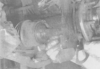
2.5. Turn the wheel away from the gearbox and remove the axle shaft. When disconnecting the inner…

2.5. Turn the wheel away from the gearbox and remove the axle shaft. When disconnecting the inner end and removing from the vehicle, support the axle shaft in position at this level


6. Using a large screwdriver or pry bar, pull the inner joint out of the transmission (see illustration).
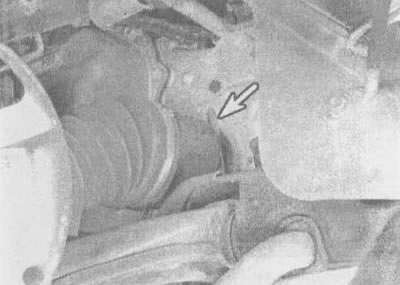
2.6 Using a large screwdriver or crowbar (indicated by the arrow), push the inner end of the axle…

2.6 Using a large screwdriver or crowbar (indicated by the arrow), push the inner end of the axle shaft out of the gearbox


7. Support the constant velocity joints and carefully remove the axle shaft from the vehicle.

Installation


8. Lubricate the differential seals with multi-purpose grease, then, while supporting the constant velocity joints, raise the axle shaft to the desired level and insert the splined end of the inner constant velocity joint into the differential axle gear. Install the shaft in the gear by placing the blade of a screwdriver in the groove of the constant velocity joint and tapping the axle shaft into place with a hammer (see illustration).
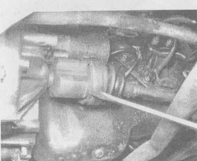
2.8 To install the constant velocity joint into the transmission, you can use a large screwdriver…

2.8 To install the constant velocity joint into the transmission, you can use a large screwdriver or punch, positioning it in the groove on the joint housing


9. Grasp the inner constant velocity joint housing (but not for the axle shaft) and pull outward to ensure the axle shaft is firmly seated in place.

10. Apply a thin coat of multi-purpose grease to the splines of the joint, pull it onto the strut/steering knuckle assembly and install the axle shaft into the hub.

11. Insert the lower control arm ball joint pin into the steering knuckle and tighten the nut. Don't forget to use a new pin (see chapter 10, section 5).

12. Install the brake disc and caliper (refer to Chapter 9 if necessary, sections 3 and 4).

13. Tighten the hub nut. Secure the disc so that it cannot rotate using a screwdriver or punch inserted through the caliper into the disc ventilation hole, and tighten the hub nut to the torque specified in the specifications in this chapter.

14. Install the wheel and lower the vehicle. Tighten the wheel nuts to the torque specified in the specifications chapters 1.

15. Install the wheel cover.

(The article is reprinted from the website chevyman.ru)

The article was checked: Vladimir Romannikov
This article is available at russian, bulgarian, belarusian, ukrainian, serbian, croatian, romanian, polish, slovak, hungarian

Share information:

Previous articles
Lumina 1: Drive shafts
Next articles

General information about drive shafts
Technical data of drive shafts
Replacement of protective covers of drive axle shafts and repair of CV joints
Internal constant velocity joint
External constant velocity joint


See similar articles on the topic of Chevrolet cars:
Support (housing) of bearings of gearbox shafts Chevrolet Aveo T250 (2006-2011)
Front axle specifications Chevrolet Captiva 1 (2006-2018)
Removal and installation axle shafts Chevrolet Niva 1 (2002-2016)
Rear axle lubrication Chevrolet Tahoe 1 (1992-2000)
Link in different formats to this page


Visitor comments

No comments yet


How much will 18 + 18 =


Orlando 1 (2010-2018) 
  • General information
  • Introduction to manual
  • User manual
  • Maintenance
  • Troubleshooting
  • Power unit
  • Engine repair
  • Fuel and control system
  • Cooling and lubrication system
  • Ignition system
  • Transmission
  • Clutch
  • Gearbox
  • Drive shafts
  • Chassis
  • Car suspension
  • Steering
  • Brake system
  • Body
  • Exterior (external elements)
  • Doors, locks and windows
  • Electrical equipment
  • Equipment and devices
  • Windscreen wipers
  • Power devices
  • Electrical diagrams


Trailblazer 1 (2001-2008) 
  • General information
  • User manual
  • Troubleshooting
  • Maintenance
  • Power unit
  • Engine in a car
  • Engine overhaul
  • Cooling and heating
  • Fuel and exhaust system
  • Engine electrical equipment
  • Engine control
  • Transmission
  • Automatic gearbox
  • Transfer case
  • Drive shafts and cardan
  • Chassis
  • Brake system
  • Car suspension
  • Steering
  • Body
  • Exterior (external elements)
  • Interior (internal elements)
  • Doors, locks and windows
  • Electrical equipment
  • Equipment and devices
  • Electrical circuits


Lumina 1 (1989-1994) 
  • General information
  • Maintenance
  • Power unit
  • Engine 3.1L V6
  • Engine 3.8L V6
  • Engine overhaul
  • Cooling system
  • Power and exhaust system
  • Fuel injection
  • Engine electrical equipment
  • Reduced exhaust gas toxicity
  • Transmission
  • Automatic gearbox
  • Drive shafts
  • Chassis
  • Brake system
  • Car suspension
  • Steering
  • Body
  • Heating and air conditioning
  • Repair of body elements
  • Doors, covers and windows
  • Interior (internal elements)
  • Electrical equipment
  • Equipment and devices
  • Electrical circuits


ChevyMan.ru © 2017-2026 · Mobile version · Feedback · Site search · Interesting to read · Sitemap: EN BG BY UA RS HR RO PL SK HU

Aveo 2003-2008 · Aveo 2006-2011 · Aveo 2012-2018 · Captiva 2006-2018 · Cruze 2008-2016 · Lacetti 2002-2009 · Lanos 2002-2009 · Niva 2002-2016 · Tahoe 1992-2000 · Tahoe 2000-2014 · Lumina 1 1989-1994 · Trailblazer 1 2001-2008 · Orlando 1 2010-2018 ·
🛡️ For your security and to improve our service, this site uses cookies. You can disable them in your browser.