


Contents: Examination ↧ Replacement ↧
Examination
Note: The brake light sensor on the described vehicles is not adjustable. If it does not work as described below, replace it.
1. Sensor (see illustration) is located on the side of the brake pedal and is secured with the same clamp as the vacuum booster rod. The sensor is designed to close the circuit of the brake lights located at the rear when the brake pedal is pressed. To access the sensor, you will need to remove the panel located on the left side under the instrument panel and the heating/air conditioning duct.
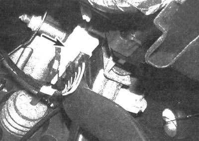
14.1. The sensor is located on the side of the brake pedal lever
2. If the sensor does not work, first check the corresponding fuse (see chapter 12).
3. If the fuse is normal, check for voltage on the sensor power wire (please refer to the wiring diagrams at the end of this manual to determine the correct wire color). If voltage is not confirmed, replace the wire connecting the sensor to the fuse box.
4. If the presence of voltage is confirmed, press the brake pedal and check for voltage at the contact terminal of the output wire (refer to the wiring diagrams again). If there is no voltage, replace the sensor.
5. If there is voltage on the output wire, check for power on the brake light wires located in the rear light housing (with the brake pedal depressed). If there is no voltage, restore the circuit between the sensor and the brake lights.
6. If voltage is present, examine the ground loop. Using a jumper wire connected to a good ground point, connect it to the ground terminal of the tail light connector. If the brake light comes on, restore the ground loop (inspect the ground wire coming out of the tail light housing).
7. Although brake light bulbs can burn out, the chances of all bulbs burning out are extremely small.
Replacement
8. If necessary, remove the panel located on the left under the instrument panel and the heating/air conditioning duct.
9. Disconnect the electrical connector from the sensor.
10. Remove the clamp that secures the sensor and the vacuum booster rod to the pin located on the brake pedal lever (see illustration 9.9) and pull the brake light sensor off the pin.
11. The sensor is installed in the reverse order of removal. Make sure the clamp is installed correctly.
(The article was reprinted from the website ChevyMan.ru)