
Warning: Dust generated by wear of the pads is hazardous to health. Do not blow it off with compressed air or inhale dust. When servicing the brake system, it is recommended to wear a protective mask or respirator. Do not use gasoline or solvents for cleaning. Use only a special product for cleaning brake system components.
1. Loosen the rear wheel nuts, jack up the rear of the vehicle and install supports. Release the parking brake. Place chocks under the front wheels to prevent the vehicle from rolling, then remove the rear wheels.
2. Remove the caliper (see subsection 4), bracket and brake disc (see subsection 5). Disengage the parking brake mechanism regulator as described in subsection 12, to ensure that the cables are slack.
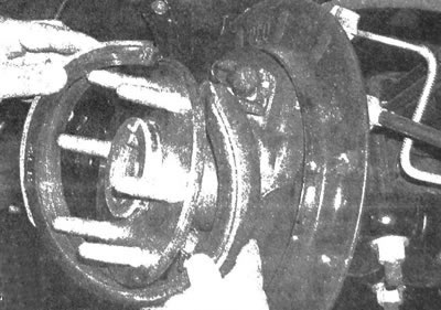
3. Clean the brake assembly with a special agent. Pull the shoe down until it disengages from the retainer (see illustration), then pull it up and disconnect it from the drive mechanism.
13.3. Pull the shoe down until it disengages from the retainer
4. Lift one end of the shoe over the axle flange, then slide it over the flange and remove the shoe (see illustration).
13.4. Lift the end of the parking brake shoe above the axle flange, then slide the shoe over it
5. Before installing a new pad, turn the toothed wheel of the adjusting screw inward, then make sure that the slots of the adjusting screw and the cone are parallel to the brake shield.
6. To install the shoe, perform the removal procedure in reverse order. Place the shoe under the clamp, then make sure that its ends are correctly positioned in the slots of the adjusting screw and cone (see illustration).
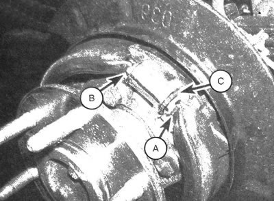
13.6.Make sure that the ends of the shoe are positioned in the cutout of the adjusting screw (A) and cone (B); the toothed wheel of the adjusting screw has the designation (C)
7. When installing a new pad, it is necessary to turn the adjusting screw so that the pad contacts the braking surface inside the disc. After this, remove the disc and move the adjusting screw back so that the pad lining does not come into contact with the installed disc when rotating. The gap between the surface of the pad and the inner braking surface of the disc should be 0.7 mm.
8. Installation is carried out in the reverse order of removal. Tighten the bracket and caliper bolts to the specified torques. Tighten the wheel nuts to the torque value given in specifications of chapter 1.
The article is based on data from the website «CHEVYMAN.ru»