


Warning: Given the increased flammability of gasoline. as well as the explosive nature of its vapors, certain precautions must be taken when performing preventive inspection and maintenance of fuel system components. Work in well-ventilated areas and do not allow open flames or light bulbs without protective covers in the work area. Do not allow gasoline to come into contact with the skin. Work with rubber gloves. If gasoline gets on your skin, wash it off with running water and soap. Wipe up spilled fuel immediately and store the absorbent cloth where it cannot be ignited. Before working on elements, release pressure in the system. Keep a class B fire extinguisher handy and wear eye protection when working with the system.
All models described have a multi-point sequential fuel injection system (SFI) (see illustration). Direct sequential fuel injection into the cylinder intake tracts occurs in accordance with synchronized pulses coming to the injectors from the electronic unit of the engine management system (PCM). After processing the signals corresponding to the engine parameters, the microprocessor calculates the optimal amount of fuel, which is supplied to the cylinder intake tracts in a certain sequence.
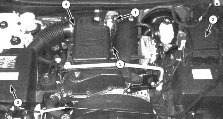
1.1 Elements of a typical fuel system 1. Throttle block; 2. Fuel pump relay (located inside the distribution block, which is located in the engine compartment); 3. Air cleaner housing; 4. Intake duct and resonator; 5. Fuel receiver and injectors (not visible from this resource)
All models use an electric fuel pump located in the fuel tank. To access the pump, the fuel tank must be removed. The fuel system measuring unit is an element of the fuel pump and is removed using the same method.
The exhaust system consists of exhaust manifolds, catalytic converter, exhaust pipes and muffler. Each of the listed elements is replaceable. The description of the catalytic collector is given in chapter 6.
[The material was created based on information from the website: CHEVYMAN.RU]