


Contents: Air conditioning and glass heating… ↧ Air conditioner fan and electric… ↧ Air Conditioning Compressor Control… ↧ Connector socket ↧
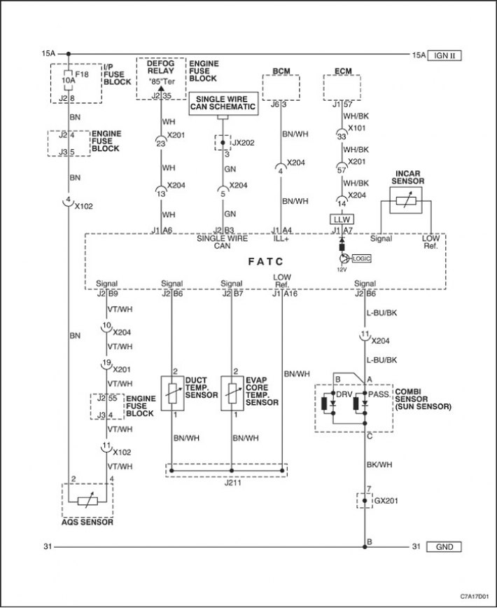
Air conditioning and glass heating sensors diagram
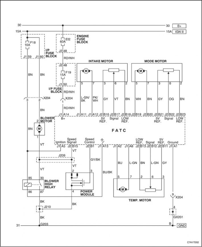
Air conditioner fan and electric motor controls diagram
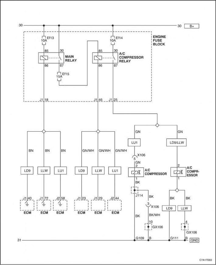
Air Conditioning Compressor Control Circuit
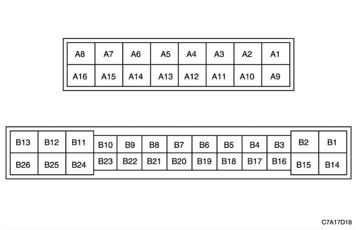
Connector socket
|
A1
|
Power supply weight
|
B6
|
Air Duct Temperature Sensor Signal
|
||
|
A2
|
Temperature control electric drive
|
B7
|
Evaporator core temperature sensor signal
|
||
|
A3
|
-
|
B8
|
Solar Irradiation Sensor Signal
|
||
|
A4
|
Lighting controller (BCM)
|
B9
|
APS sensor signal
|
||
|
A5
|
IGN II (15 A)
|
B10
|
-
|
||
|
A6
|
Glass heating relay
|
B11
|
Temperature actuator, 5V reference.
|
||
|
A7
|
Communication with the ECM
|
B12
|
Temperature actuator signal
|
||
|
A8
|
Temperature control electric drive
|
B13
|
Temperature actuator mass
|
||
|
A9
|
-
|
B14
|
-
|
||
|
A10
|
-
|
B15
|
Power module (speed signal)
|
||
|
A11
|
Intake manifold control actuator
|
B16
|
Intake Electric Actuator, 5V Reference.
|
||
|
A12
|
Intake manifold control actuator
|
B17
|
Intake manifold signal
|
||
|
A13
|
High Speed Fan Relay Ground Control
|
B18
|
Mass of the intake actuator
|
||
|
A14
|
Fuse "F19" (BAT)
|
B19
|
Control electric drive mode
|
||
|
A15
|
-
|
B20
|
Control electric drive mode
|
||
|
A16
|
Air Duct Temperature/Evaporator Core Temperature Mass
|
B21
|
Electric drive mode, 5 V reference.
|
||
|
B1
|
Power module (speed control)
|
B22
|
Electric drive mode signal
|
||
|
B2
|
-
|
B23
|
Electric drive mode weight
|
||
|
B3
|
Single-wire CAN
|
B24
|
-
|
||
|
B4
|
-
|
B25
|
-
|
||
|
B5
|
-
|
B26
|
-
|
||
[Information taken from the official website CHEVYMAN.RU]