


Contents: Automatic temperature controller… ↧ The regulator does not light up when… ↧ The electric fan does not work at all ↧ Without air source selection control ↧ Without air source selection control ↧ Table of parameters of the intake… ↧ The compressor electromagnetic… ↧ The compressor electromagnetic… ↧
See in section 7B, "Manually Controlled Heating, Ventilating, and Air Conditioning System" detailed information on the following procedures:
- Checking the quality of the air conditioner operation.
- Quick check procedure for insufficient cooling.
- Diagnosis of insufficient cooling.
- Checking for leaks in the refrigeration system.
- Graph of the dependence of pressure values on the high and low pressure sides.
- Pressure check card (r-134A system).
- Pressure-temperature dependence of R-134a.
- Checking the refrigeration system.
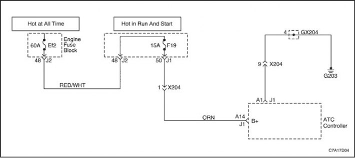
Automatic temperature controller does not function when ignition is on
| Step | Operation | Values | Yes | No |
| 1 |
Check fuse EF2.
Is the EF2 fuse blown?
|
-
|
Jump to operations 2
|
Jump to operations 3
|
| 2 |
Replace fuse EF2.
Is the renovation finished?
|
-
|
The system is normal
|
-
|
| 3 |
Is the measured voltage within the specified range?
|
11-14 V
|
Jump to operations 4
|
Jump to operations 5
|
| 4 |
Is the renovation finished?
|
-
|
The system is normal
|
-
|
| 5 |
Check the voltage between terminal A1 and ground.
Is the voltage as specified?
|
0 B
|
Jump to operations 6
|
Jump to operations 7
|
| 6 |
Is the renovation finished?
|
-
|
The system is normal
|
-
|
| 7 |
Is the renovation finished?
|
-
|
The system is normal
|
-
|
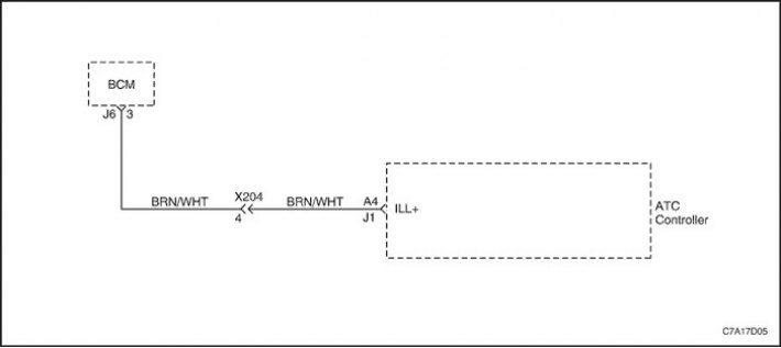
The regulator does not light up when the light switch is on
| Step | Operation | Values | Yes | No |
| 1 |
Check the backlighting of the remaining devices.
The backlight of the other instruments is also not on?
|
-
|
Jump to operations 2
|
|
| 2 |
Is the measured voltage within the specified range?
|
11-14 V
|
Jump to operations 4
|
Jump to operations 3
|
| 3 |
Repair damage to the wiring harness between terminal 3 on the J6 connector and terminal A4 on the regulator connector.
Is the renovation finished?
|
-
|
The system is normal
|
-
|
| 4 |
Check the backlight lamps.
Is the light bulb burnt out?
|
-
|
Jump to operations 5
|
Jump to operations 6
|
| 5 |
Replace the burnt-out backlight lamp.
Is the renovation finished?
|
-
|
The system is normal
|
-
|
| 6 |
Replace the automatic temperature controller (ATC).
Is the renovation finished?
|
-
|
The system is normal
|
-
|
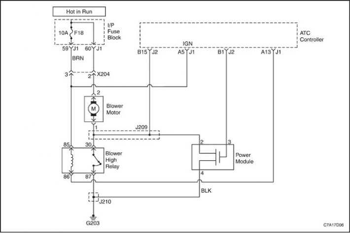
The electric fan does not work at all
| Step | Operation | Values | Yes | No |
| 1 |
Do the numbers light up and go out?
|
-
|
Jump to operations 2
|
Jump to operations 3
|
| 2 |
Perform a self-diagnostic circuit check.
Is there a fault code displayed on the indicator?
|
-
|
Go to the troubleshooting table for the code that is flashing.
|
-
|
| 3 |
Check fuse F18 in the instrument panel fuse box.
Is this fuse in normal condition?
|
-
|
Jump to operations 5
|
Jump to operations 4
|
| 4 |
Replace fuse F18.
Is the renovation finished?
|
-
|
The system is normal
|
-
|
| 5 |
Is the measured voltage within the specified range?
|
11-14 V
|
Go to operations 15
|
Jump to operations 8
|
| 6 |
Measure the voltage between ground and terminal 30 (BRN/WHT) of the fan relay.
Is the measured voltage within the specified range?
|
11-14 V
|
Jump to operations 8
|
Jump to operations 7
|
| 7 |
Eliminate any faults found at terminal 85 of the relay connector or ground G203.
Is the renovation finished?
|
-
|
The system is normal
|
-
|
| 8 |
Replace the fan relay.
Is the renovation finished?
|
-
|
The system is normal
|
-
|
| 9 |
Is the measured voltage within the specified range?
|
11-14 V
|
Jump to operations 11
|
Jump to operations 10
|
| 10 |
Is the renovation finished?
|
-
|
The system is normal
|
-
|
| 11 |
Measure the resistance between the terminals of the connector on the electric fan.
Does the measured resistance correspond to that indicated in the table?
|
≈ 5 Ohm
|
Jump to operations 13
|
Go to operations 12
|
| 12 |
Replace the electric fan.
Is the renovation finished?
|
-
|
The system is normal
|
-
|
| 13 |
Measure the resistance of the circuit between terminal 1 of the fan connector and terminal 30 of the maximum speed relay, as well as terminal 2 of the power module.
Does the measured resistance correspond to that indicated in the table?
|
≈ 0 Ohm
|
Go to operations 15
|
Jump to operations 14
|
| 14 |
Correct any problems found in the circuit.
Is the renovation finished?
|
-
|
The system is normal
|
-
|
| 15 |
Measure the resistance of the circuit between terminal 4 of the power module connector and ground.
Does the measured resistance correspond to that indicated in the table?
|
0 Ohm
|
Jump to operations 17
|
Jump to operations 16
|
| 16 |
Is the renovation finished?
|
-
|
The system is normal
|
-
|
| 17 |
Replace the automatic temperature controller (ATC).
Is the renovation finished?
|
-
|
The system is normal
|
-
|
Without air source selection control
See the electrical diagram for the circuits described in this procedure in the section "Scheme of the air conditioner fan and control electric drives".
Without air source selection control
| Step | Operation | Values | Yes | No |
| 1 |
Measure the voltage at terminal 4 of the intake actuator.
Is the voltage within the set value?
|
11-14 V
|
Jump to operations 3
|
Jump to operations 2
|
| 2 |
Is the renovation finished?
|
-
|
The system is normal
|
-
|
| 3 |
Do the voltages match the specified values?
|
See "Intake Electric Actuator Parameter Table"
|
Jump to operations 4
|
Jump to operations 5
|
| 4 |
Replace the intake actuator.
Is the renovation finished?
|
-
|
The system is normal
|
-
|
| 5 |
Do the voltages match the specified values?
|
See "Intake Electric Actuator Parameter Table"
|
Jump to operations 6
|
Jump to operations 7
|
| 6 |
Is the renovation finished?
|
-
|
The system is normal
|
-
|
| 7 |
Check the connector on the regulator.
Is a damaged contact found?
|
-
|
Jump to operations 8
|
Jump to operations 9
|
| 8 |
Repair or replace the connector.
Is the renovation finished?
|
-
|
The system is normal
|
-
|
| 9 |
Replace the regulator.
Is the renovation finished?
|
-
|
The system is normal
|
-
|
Table of parameters of the intake electric drive
|
Intake mode
|
Intake Electric Drive
|
||
|
|
Connector pinout
|
||
|
Regulator/motor
|
Regulator/motor
|
Regulator/motor
|
|
|
B14/7
|
A15/6
|
B13/5
|
|
|
Recirculation
|
0 B
|
11-14 V
|
11-14 V
|
|
Ventilation 1/3
|
11-14 V
|
0 B
|
11-14 V
|
|
Ventilation
|
11-14 V
|
11-14 V
|
0 B
|
The compressor electromagnetic clutch does not engage
Refer to the "A/C Compressor Control Circuit, SOHC" or "A/C Compressor Control Circuit, DOHC" sections for the electrical diagram of the circuits described in this procedure.
The compressor electromagnetic clutch does not engage
| Step | Operation | Values | Yes | No |
| 1 |
Is the measured voltage within the specified range?
|
11-14 V
|
Go to item "Diagnosing Insufficient Cooling"
|
Jump to operations 2
|
| 2 |
Replace the automatic temperature controller (ATC).
Is the renovation finished?
|
-
|
The system is normal
|
-
|