


Contents: Disassembly procedure ↧ Assembly order ↧
Necessary equipment
- J-42991 Strut Rod Nut Socket or Equivalent
- J-45400 Strut Spring Compressor or equivalent
Disassembly procedure
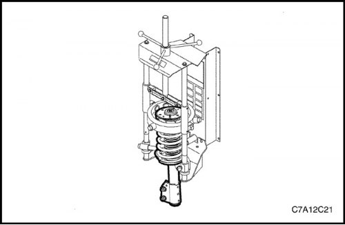
1. Install the strut assembly into the J-45400 using the following procedure.
- Position the lower legs of the J-45400 against the lowest accessible coil of the spring.
- Position the top legs of the J-45400 against the topmost accessible coil of the spring.
- Check the strut assembly to ensure that the strut compression lugs are properly seated on the spring coils.
- Make sure the strut assembly is parallel to J-45400.
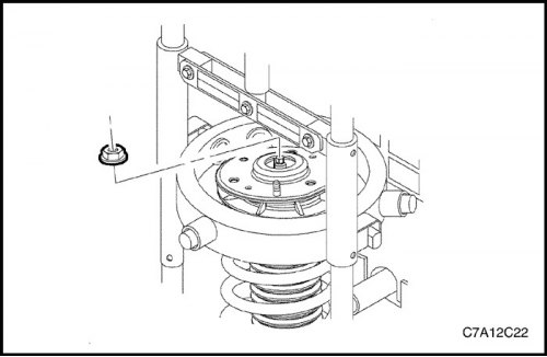
2. Compress the spring enough to relieve the upper support of the strut.
Note: Do not allow the front suspension strut stud to rotate during disassembly/reassembly. Use hand tools to prevent the strut stud from rotating. If air tools are used and the stud is allowed to rotate, it may cause damage to the strut.
3. Use J-42991 or equivalent hand tools to remove the strut rod retaining nut.
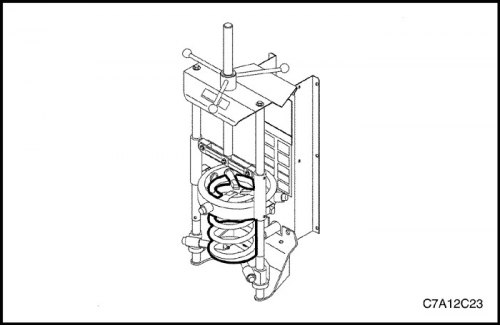
Important: Leave the spring in the puller.
4. Lower the strut from the spring assembly.
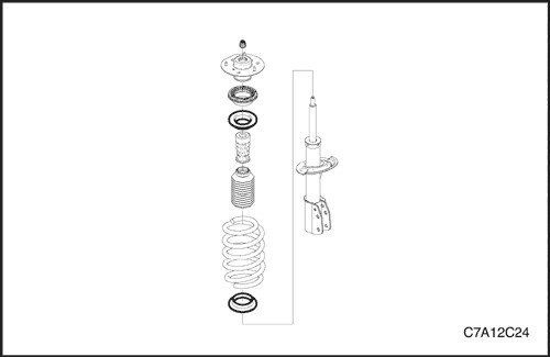
Note: Do not use the plastic part when working on the upper support assembly. When working on the upper support assembly, use the metal part when removing the upper support from the telescopic strut assembly / installing it on the strut assembly. Using the plastic part when working on the upper support assembly may weaken the snapping of the bearing elements and cause the bearing to fall apart.
5. Remove the upper support assembly, check for damage and wear. Replace if necessary.
6. Remove the strut dust shield and inspect for damage or wear. Replace if necessary.
7. Remove the buffer with the hole from the strut rod and inspect for damage and wear. Replace if necessary.
8. Check if the spring is damaged. Replace if necessary.

Assembly order
1. Extend the rack to the limit of its travel.
2. Install the buffer with the hole and the dust cover on the strut rod.
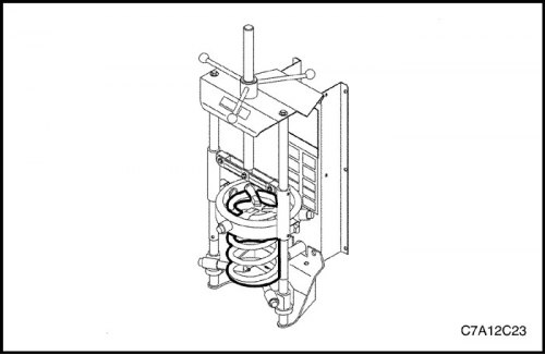
Important: The mark with the spring designation will be closer to the bottom of the spring. The end of the coil sits opposite the protrusion on the spring support cup.
3. Install the strut into the spring located in the puller.
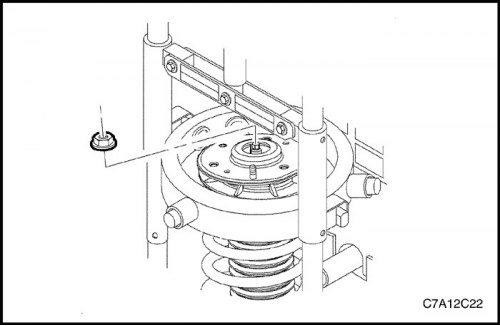
Important: The rotation locking lug on the spring support cup must be at an angle of 180 degrees to the direction the steering knuckle bracket points.
4. Assemble the upper spring support cup with the strut rod installation and align the flat edge with the strut-to-steering knuckle mounting bracket.
Note: Do not use the plastic part when working on the upper support assembly. When working on the upper support assembly, use the metal part when removing the upper support from the telescopic strut assembly / installing it on the strut assembly. Using the plastic part when working on the upper support assembly may weaken the snapping of the bearing elements and cause the bearing to fall apart.
Important: The flat edge on the metal plate of the upper support assembly must face in the same direction as the rotation locking tab on the spring support cup.
5. Assemble the upper support with the strut rod and align the flat face at 180 degrees with the face on the upper spring support cup.
6. Install the strut rod mounting nut.
Note: Do not allow the front suspension strut stud to rotate during disassembly/reassembly. Use hand tools to prevent the strut stud from rotating. If air tools are used and the stud is allowed to rotate, it may cause damage to the strut.
7. While holding the strut rod, use J-42991 or equivalent hand tools to tighten the rod while ensuring the flats on the upper spring seat cup are aligned with the upper seat.
Tighten
Tighten the strut rod mounting nut to 75 N·m (55 ft·lbs).
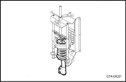
8. Loosen tension on J-45400.
9. Remove the telescopic strut assembly from J-45400.