
Contents: Removal procedure ↧ Installation procedure ↧
Removal procedure
1. Remove the rear brake caliper assembly and disc. See Part 4E. Rear brakes.
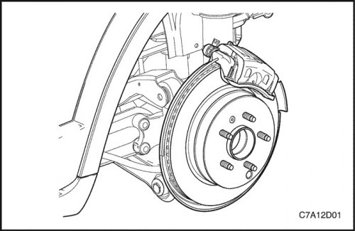
2. On all-wheel drive vehicles, remove the drive shaft spindle nut.
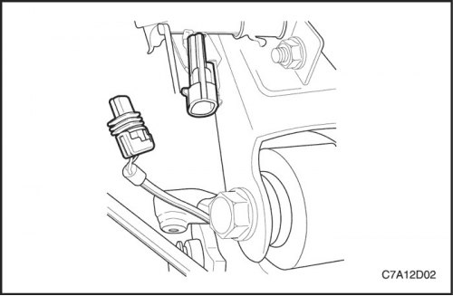
3. Disconnect the wheel speed sensor electrical connector.

Important: Do not damage the protective cover of the drive shaft joint.
4. Secure the drive shaft with strong wire or similar.
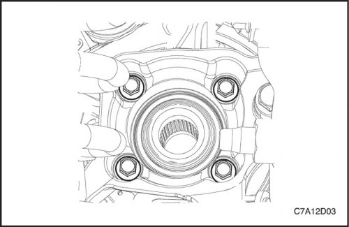
5. Remove the wheel bearing/hub mounting bolts.
6. Remove the wheel bearing/hub assembly from the suspension knuckle.
7. Remove the wheel speed sensor from the wheel bearing/hub assembly. See Section 4F. Anti-lock braking system.
Installation procedure
1. Install the wheel speed sensor to the wheel bearing/hub assembly.
2. Install the wheel bearing/hub assembly onto the steering knuckle.
3. Install the wheel bearing/hub mounting bolts.
Tighten
Tighten the bolts to 84 Nm (62 ft·lbs).

4. On all-wheel drive vehicles, install the drive shaft spindle nut.
Tighten
Tighten the nut to a torque of 205 N·m (151 lb-ft).

5. If the wheel speed sensor electrical harness is included, route it through the brake shield and secure the grommet.
6. Connect the wheel speed sensor electrical connector.
7. Install the rear wheel brake drum.