
ChevyMan.ru
Mazda Mitsubishi Toyota Land Rover Honda Kia Nissan
English Русский
Български
Беларускі
Український
Српски
Hrvatski
Română
Polski
Slovenský
Magyar
|
Articles | Sitemap | Contacts |


Home   Aveo   Captiva   Cruze   Lacetti   Lanos   Niva   Tahoe   Others  
Captiva 1 (2006-2018)
  • Home
  • Captiva
  • 1 (2006-2018)
  • Engine HFV6 3.2L
  • Control and power systems
  • Fuel pump assembly

Fuel pump assembly (Chevrolet Captiva 1)

            0

Contents: Removal procedure ↧ Installation procedure ↧

Necessary equipment


Main Fuel Pump Lock Ring Remover/Installer EN-48279

Tool for removing/installing locking rings of the reserve fuel pump EN-48278

Removal procedure


Caution! The fuel system is under pressure. Before disconnecting the fuel lines, relieve the pressure in the fuel supply system to avoid fuel spillage and burns.


1. Relieve pressure in the fuel supply system. See "Relieving pressure in the fuel supply system"

2. Disconnect the negative battery cable.

3. Fold the rear seat.

4. Lift the mat and insulation.

5. Remove the covers to access the main and backup fuel pumps.
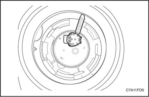
5. Remove the covers to access the main and backup fuel pumps.


6. Disconnect the electrical connector from the backup fuel pump assembly.
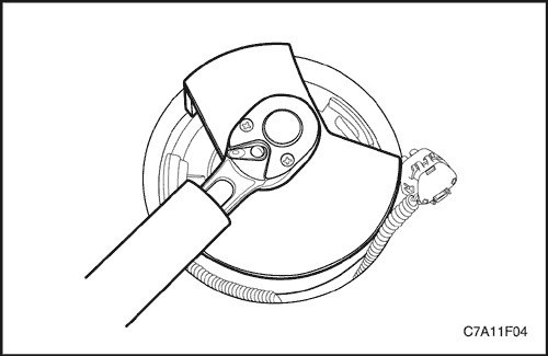
6. Disconnect the electrical connector from the backup fuel pump assembly.


7. Install the EN-48278 standby fuel pump lock ring remover/installer onto the standby fuel pump and turn it counterclockwise.


8. Remove the backup fuel pump retaining ring.

Note: Be careful not to damage the fuel sensor when removing the fuel pump assembly from the fuel tank.


9. Remove the backup fuel pump assembly and sealing ring from the fuel tank.

Note: The sealing ring must not come into contact with the fuel.
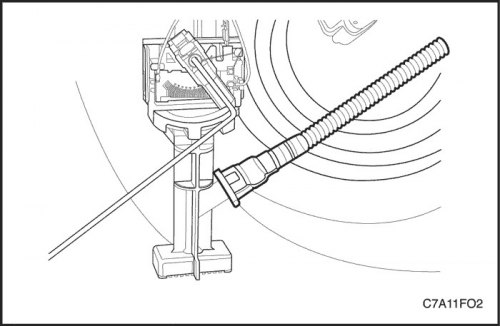

Note: The sealing ring must not come into contact with the fuel.


10. Disconnect the connecting hose connecting the main fuel pump to the backup fuel pump from the backup fuel pump.
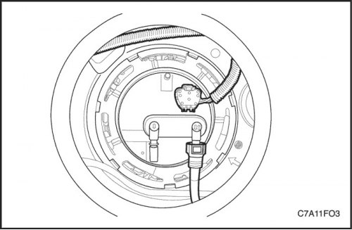
10. Disconnect the connecting hose connecting the main fuel pump to the backup fuel pump from the…


11. Disconnect the electrical connector from the main fuel pump.

12. Disconnect the fuel line.
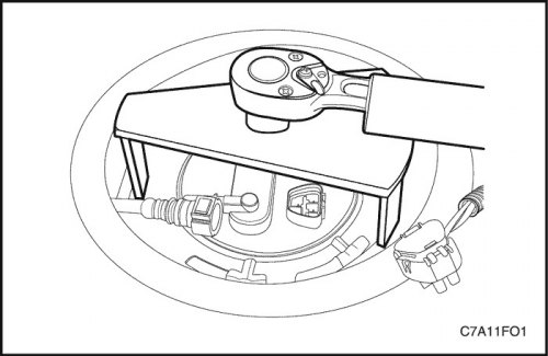
12. Disconnect the fuel line.


13. Install the EN-48279 Main Fuel Pump Lock Ring Remover/Installer onto the main fuel pump and turn it counterclockwise.


14. Remove the main fuel pump retaining ring.

Note: Be careful not to damage the fuel sensor when removing the fuel pump assembly from the fuel tank.


15. Remove the main fuel pump assembly and sealing ring from the fuel tank.

Note: The sealing ring must not come into contact with the fuel.
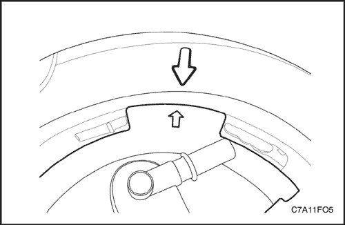

Note: The sealing ring must not come into contact with the fuel.


Installation procedure


1. Clean all seal contact surfaces on both fuel pumps and in the fuel tank.

Note: To make it easier to connect the connecting hose that connects the main fuel pump to the backup fuel pump, install the main fuel pump assembly first.


Note: Make sure the arrow on the main fuel pump assembly aligns with the arrow on the fuel tank.


Note: Be careful not to damage the fuel sensor when installing the fuel pump assembly into the fuel tank.


Caution: Do not reuse the main fuel pump O-ring.


2. First place the new main fuel pump O-ring and main fuel pump into the fuel tank in the same position as before removal.
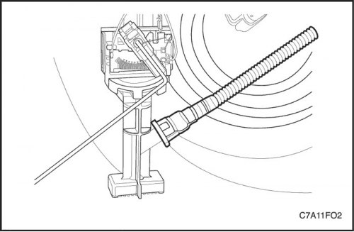
2. First place the new main fuel pump O-ring and main fuel pump into the fuel tank in the same…


3. Remove the connecting hose connecting the main fuel pump and the standby fuel pump from the standby fuel pump assembly.


4. Connect the connecting hose from the main fuel pump to the backup fuel pump to the backup fuel pump.
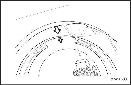
4. Connect the connecting hose from the main fuel pump to the backup fuel pump to the backup fuel…


Note: Make sure the arrow on the backup fuel pump assembly housing aligns with the arrow on the fuel tank.


Note: Be careful not to damage the fuel sensor when installing the fuel pump assembly into the fuel tank.


Caution: Do not reuse the backup fuel pump O-ring.


5. Place the new backup fuel pump O-ring and backup fuel pump into the fuel tank in the same position as before removal.
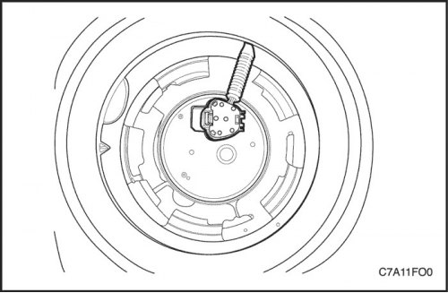
5. Place the new backup fuel pump O-ring and backup fuel pump into the fuel tank in the same…


6. Install the reserve fuel pump lock ring by turning the EN-48278 lock ring remover/installer clockwise.

7. Connect the electrical connector to the backup fuel pump.
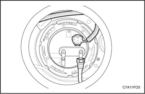
7. Connect the electrical connector to the backup fuel pump.


8. Install the main fuel pump lock ring by turning the EN-48279 main fuel pump lock ring remover/installer clockwise.


9. Connect the electrical connector to the main fuel pump.

10. Connect the fuel line.
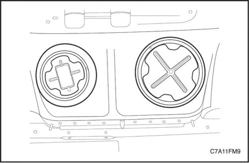
10. Connect the fuel line.


11. Install the access covers to the main and backup fuel pumps.

12. Connect the negative battery cable.

13. Check the functionality of the fuel pump.

14. Return the rear seats to their original position.
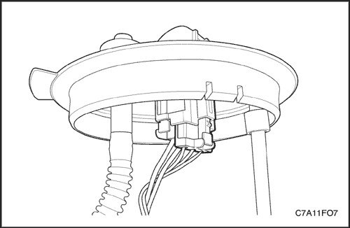
14. Return the rear seats to their original position.


(The original text can be found on the website «ChevyMan.ru»)

The article was checked: Vladimir Romannikov
This article is available at russian, bulgarian, belarusian, ukrainian, serbian, croatian, romanian, polish, slovak, hungarian

Share information:

Previous articles
Captiva 1: Control and power systems
Next articles

Fuel tank — removal and installation
Checking fuel pressure
Relieving pressure in the fuel supply system
Diagnosing signs of engine management system malfunctions
Diagnostic Trouble Codes (DTC)
Fuel level sensor
Fuel filter
Fuel rail assembly
Ignition coil
Spark plugs


See similar articles on the topic of Chevrolet cars:
Installing a fuel pump Chevrolet Aveo T250 (2006-2011)
Fuel injection system faults Chevrolet Cruze 1 (2008-2016)
Replacing the fuel filter Chevrolet Lacetti 1 (2002-2009)
Checking the fuel pump activation circuit Chevrolet Lanos T150 (2002-2009)
Fuel tank cap Chevrolet Niva 1 (2002-2016)
Fuel Pump/Fuel Pressure — Check Chevrolet Tahoe 1 (1992-2000)
Checking the fuel pump and fuel pressure Chevrolet Lumina 1 (1989-1994)
Link in different formats to this page


Visitor comments

No comments yet


How much will 43 + 27 =


Captiva 1 (2006-2018) 
  • Manual
  • Before leaving
  • Keys, doors and windows
  • Seats, protection systems
  • Instruments and controls
  • Lighting system
  • Information and entertainment
  • Navigation system
  • Climate control
  • Driving a car
  • Car care
  • Maintenance
  • Engine 2.0 l (diesel)
  • Engine device
  • Troubleshooting
  • Engine repair
  • Cooling system
  • Engine electrical equipment
  • Control and power systems
  • Exhaust system
  • Engine FAM II 2.4D
  • Engine device
  • Troubleshooting
  • Engine repair
  • Cooling system
  • Engine electrical equipment
  • Control and power systems
  • Exhaust system
  • Engine HFV6 3.2L
  • Engine device
  • Troubleshooting
  • Engine repair
  • Cooling system
  • Engine electrical equipment
  • Control and power systems
  • Exhaust system
  • Transmission
  • Front drive axle
  • Rear drive axle
  • Automatic gearbox - device
  • Automatic gearbox - service
  • Automatic gearbox - repair
  • Manual gearbox - device
  • Manual gearbox - service and repair
  • Clutch
  • Transfer case
  • Chassis
  • Car suspension
  • Brake system
  • Steering
  • Body
  • Heating and ventilation
  • Air conditioning (manual)
  • Air conditioning (automatic)
  • Seat belts
  • Airbags
  • Car seat
  • Interior (internal elements)
  • Exterior (external elements)
  • Doors and windows
  • Electrical equipment
  • Equipment and devices
  • Lighting and lamps
  • Windshield wipers and washers
  • Electrical circuits


ChevyMan.ru © 2017-2026 · Mobile version · Feedback · Site search · Interesting to read · Sitemap: EN BG BY UA RS HR RO PL SK HU

Aveo 2003-2008 · Aveo 2006-2011 · Aveo 2012-2018 · Captiva 2006-2018 · Cruze 2008-2016 · Lacetti 2002-2009 · Lanos 2002-2009 · Niva 2002-2016 · Tahoe 1992-2000 · Tahoe 2000-2014 · Lumina 1 1989-1994 · Trailblazer 1 2001-2008 · Orlando 1 2010-2018 ·
🛡️ For your security and to improve our service, this site uses cookies. You can disable them in your browser.