


To check, assemble the circuit according to Figure 7-7. Disconnect the common terminal wire of the three additional diodes from the "D+" plug of the voltage regulator and take measures to ensure that the tip of the disconnected wire does not short-circuit with the generator ground. Connect the wire from the storage battery to the "D+" plug of the regulator through switch 1. Thus, the excitation winding will be powered only from the storage battery.
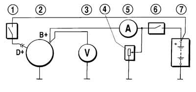
Figure 7-7. Connection diagram for testing the generator with an oscilloscope:
1 - switch;
2 - generator;
3 - voltmeter;
4 - rheostat;
5 - ammeter;
6 - switch;
7 - battery.
Turn on the stand's electric motor and increase the rotor speed to 1500-2000 min⁻¹. Using switch 6, disconnect the battery from the "B+" terminal of the generator and use rheostat 4 to set the output current to 10 A.
Check the voltage on the "B+" terminal of the generator using an oscilloscope. If the diodes and stator winding are in good condition, the rectified voltage curve has a sawtooth shape with uniform teeth (figure 7-8, I). If there is a break in the stator winding or a break or short circuit in the rectifier block diodes, the shape of the curve changes dramatically: the uniformity of the teeth is disrupted and deep depressions appear (figure 7-8, II and III).
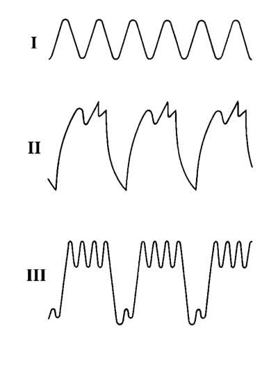
Figure 7-8. Generator rectified voltage waveform:
I - the generator is working;
II - diode is broken;
III - open circuit in the diode circuit (stator winding).
Having checked the shape of the voltage curve at the "B+" terminal of the generator and having made sure that it has a normal appearance, check the voltage at the "D" plug of the generator with the wire disconnected from the "D+" plug of the voltage regulator. The "D" plug is the common terminal of three additional diodes (see figure 7-5), supplying the excitation winding when the generator is running. The voltage curve shape here should also have a regular sawtooth shape. An incorrect curve shape indicates damage to the additional diodes.