


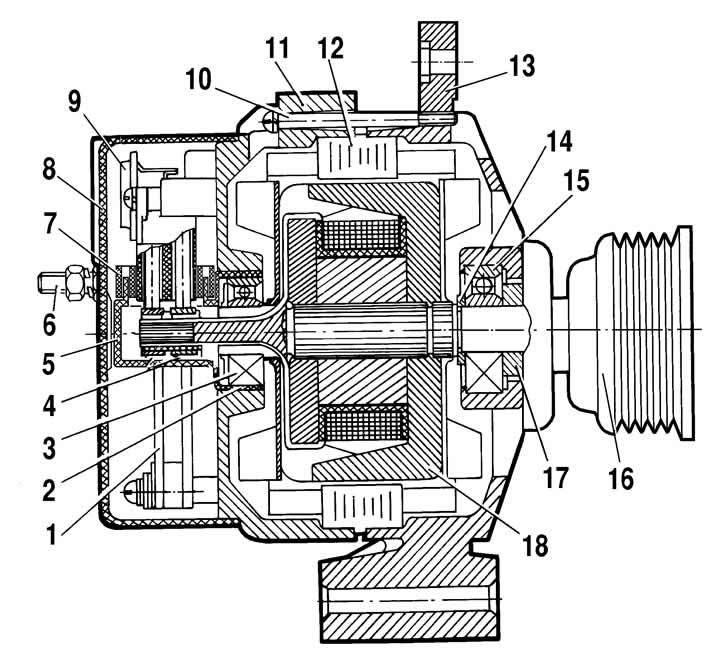
Figure 7-4. Generator 9402.3701-01:
1 - rectifier block;
2 - bearing sleeve;
3 - rear rotor shaft bearing;
4 - contact rings;
5 - protective sleeve;
6 - "B+" terminal of the generator;
7 - gasket;
8 - casing;
9 - voltage regulator with brush holder;
10 - tension screw;
11 - back cover;
12 - stator;
13 - front cover;
14 - distance ring;
15 - front bearing;
16 - pulley;
17 - washer;
18 - rotor.
Stator 12 (figure 7-4) and covers 11 and 13 are tightened with four screws. Rotor shaft 18 rotates in bearings 3 and 15, which are installed in the covers. Power to the rotor winding (excitation winding) is supplied through brushes and contact rings 4.
Three-phase alternating current induced in the stator winding is converted into direct current by rectifier unit 1, attached to cover 11. Electronic voltage regulator 9 is combined into one unit with a brush holder and is also attached to cover 11.
The generator connection diagram is shown in Figure 7-5. The voltage for excitation of the generator when the ignition is turned on is supplied to the "D+" terminal of the regulator (the "D" terminal of the generator) through the control lamp located in the instrument cluster 3. After the engine is started, the excitation winding is supplied with power from three additional diodes installed on the rectifier block of the generator.
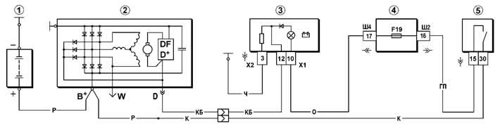
Figure 7-5. Generator system connection diagram:
1 - battery;
2 - generator;
3 - battery charge indicator lamp located in the instrument cluster;
4 - mounting block;
5 - ignition switch.
The "W" terminal of the generator is not used on Chevrolet Niva vehicles.
The generator operation is controlled by a control lamp in the instrument cluster. When the ignition is turned on, the lamp should light, and after the engine starts, it should go out if the generator is in good condition. Bright burning of the lamp or its glow at half-intensity indicates malfunctions.
Warning. The negative terminal of the battery must always be connected to ground, and the positive terminal must always be connected to the B+ terminal of the alternator. Incorrectly reconnecting the battery will immediately cause an increased current through the alternator rectifier unit.
The generator must not be operated with the battery disconnected. This will cause short-term overvoltages on the "B+" terminal of the generator, which may damage the generator voltage regulator and electronic devices in the vehicle's on-board network.
It is prohibited to check the generator's performance "for a spark" even by briefly connecting the "B+" clamp of the generator to ground. In this case, a significant current flows through the rectifier block of the generator and it can fail. The generator can only be checked using an ammeter and voltmeter.
The generator rectifier block must not be tested with a voltage higher than 12 V or with a megohmmeter, as it has a voltage that is too high for the diodes and they will be broken during testing (a short circuit will occur).
It is prohibited to check the vehicle's electrical wiring with a megohmmeter or a lamp powered by a voltage greater than 12 V. If such a check is necessary, then the wires should first be disconnected from the generator.
The insulation resistance of the generator stator winding should be checked with increased voltage only on a test bench and necessarily with the phase winding terminals disconnected from the generator rectifier unit.
When electric welding car body components and parts, you should disconnect the wires from all terminals of the generator and battery.